Installation 9 – Emerson 400518-01 User Manual
Page 21
Installation
9
Safety Information
Product Overview
Installation
Diagnostics
Options and
Accessories
Specification
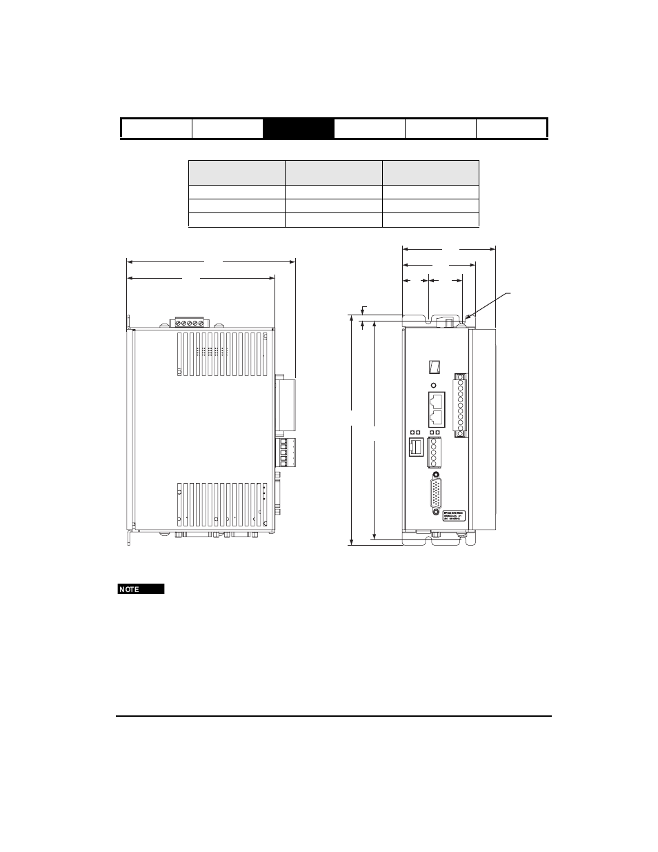
The following table applies to the "A" dimension as shown in figure 5 for the programming drives.
Figure 5:
Mechanical Drawing for Epsilon Programming Drive
To prevent drive from dropping out of position during installation, partially pre-install lower mounting screws,
then set drive in place with lower mounting screws in slots and then install at least one upper mounting screw.
For removal, loosen lower screws, remove upper screws and lift drive out.
Drive Model
Dimension "A"
inches [mm]
Minimum Panel Width
inches [mm]
EP202-Pxx-xxxx
2.69 [68.3]
3.45 [88]
EP204-Pxx-xxxx
2.69 [68.3]
3.45 [88]
EP206-Pxx-xxxx
3.40 [86.4]
4.15 [105]
2.69
[68.3]
1.20
[30.48]
1.03
[26.16]
8.099
[205.72]
7.70
[195.58]
.200
[5.08]
(4X)Ø.219
[5.56]
“A”
5.22
[132.59]
5.94
[150.88]