Panel layout, Installation 5, Figure 2: ac filter and cable connections – Emerson 400518-01 User Manual
Page 17
Installation
5
Safety Information
Product Overview
Installation
Diagnostics
Options and
Accessories
Specification
• You should consider future troubleshooting and repair when installing all wiring. All wiring should be either color
coded and/or tagged with industrial wire tabs.
• As a general rule, the minimum cable bend radius is ten times the cable outer diameter.
• All wiring and cables, stationary and moving, must be protected from abrasion.
• Ground wires should not be shared or "daisy-chained" with other equipment.
• Ensure that full metal to metal surface contact is made between the enclosure ground lug and the metal
enclosure, not simply through the mounting bolt and threads.
• All inductive coils must be suppressed with appropriate devices, such as diodes or resistor/capacitor (RC)
networks, except as described in this manual.
• If using a non-shielded Ethernet cable, install a clamp on ferrite, Control Techniques part number 157016-07,
Steward 28A0593-0A2 or equivalent.
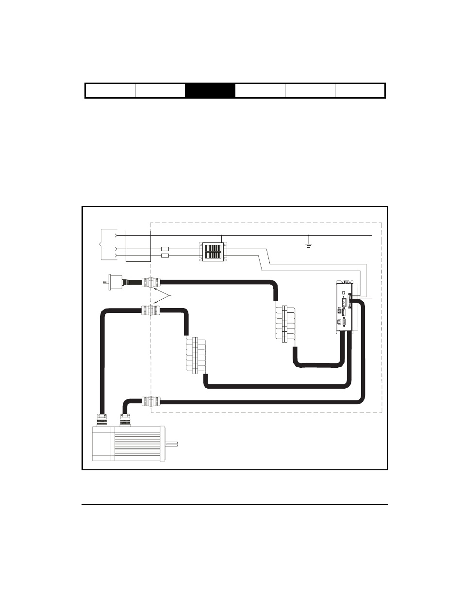
Panel Layout
Figure 2:
AC Filter and Cable Connections
External Encoder
Customer supplied
terminal strip (optional)
Connect shield through
and to mounting plate
Motor Feedback Cable
Motor Power Cable
Bonded to mounting plate
and enclosure wall
Drive
Motor
Filter
Fuses
AC In
PE
L2
L1
Through wall shield grommets
NEMA Enclosure
Metallic
Raceway