3 using monitor points – ProSoft Technology PTQ-104S User Manual
Page 136
Reference
48TPTQ-104S Rev 1 ♦ 47TQuantum Platform
12TUser Manual
46TIEC 60870-5-104 Server for Quantum
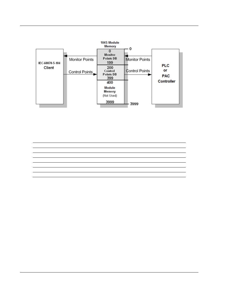
The following illustration shows an example configuration:
In this example, all monitor points are located between database addresses 0
and 199, and all control points are located between address 200 and 399.
9.2.3 Using Monitor Points
The following monitor points are supported by the PTQ-104S module:
M-SP-NA
Monitored Single-Points
1 bit
Bit
M-DP-NA
Monitored Dual-Points
2 bits
Bit
M-ST-NA
Monitored Step-Points
1 byte
Byte
M-ME-NA
Monitored Measured Normalized-Points
1 word
Word
M-ME-NB
Monitored Measured Scaled-Points
1 word
Word
M-ME-NC
Monitored Measured Short Floating Points
2 words
Double-Word
M-IT-NA
Monitored Counter-Points
2 words
Double-Word
Each monitor point is identified by its Information Object Address (it should be
unique for each Common ASDU Address in the network). For each monitor point,
configure the following parameters:
Point # - The information object address of the point. It identifies the point in the
network.
DB Address - The database location in the PTQ-104S module associated with
the point. You must associate each point to a database address in the PTQ-104S
module. The interpretation of this parameter depends on the point type
configured. For example, for an M_SP_NA point, this value represents the bit
address. For a M_ME_NA point, this value represents the Word address.
Group(s) - This is the group definition for the point. It sets how the point will be
polled by the Master (cyclic or group interrogation). It can also be used to enable
or disable the event generation for one specific point. The group parameter is
discussed in the Data Communication section.
Deadband - Sets the deadband for each measured point. If the value changes
from more than the configured deadband, the module will generate an event for
this point.
Page 136 of 201
ProSoft Technology, Inc.
March 4, 2013