ProSoft Technology MVI69-GEC User Manual
Page 59
MVI69-GEC ♦ CompactLogix or MicroLogix Platform
Contents
User Manual
ProSoft Technology, Inc.
Page 59 of 86
February 18, 2014
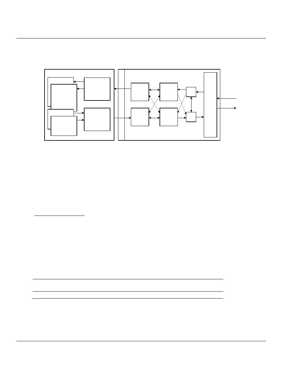
The following illustration shows the data transfer method used to move data between the
processor, the MVI69-GEC module, and the Ethernet network.
TCP/IP
Stack
and
Ethernet
Interface
Clients
TCP/IP
Servers
Transmit
Driver
Logic
Receive
Driver
Logic
Input
Image
Output
Image
MVI69-GEC Module
B
a
c
k
p
la
n
e
D
riv
e
r
Ethernet
Network
Ladder logic
transfers data
from Processor’s
data objects to
Output image
Ladder logic
transfers data
from Module’s
Input image to
data objects in
the Processor
Status
Read Data
Write Data
Special
Control Blocks
CompactLogix Processor
Controller Tags
As shown in the previous diagram, all data transferred between the module and the
processor over the backplane is through the input and output images. Ladder logic must be
written in the processor to interface the input and output image data defined in the controller
tags. The user is responsible for handling and interpreting all data received on the
application ports and transferred to the input image. Additionally, the user is responsible for
constructing messages to be transferred out of the servers by building the messages in the
output image of the module.
Normal Data Transfer
Normal data transfer includes the transferring of data received or to be transmitted on the
servers and the status data. These data are transferred through read (input image) and write
(output image) blocks. Refer to Module Configuration for a description of the data objects
used with the blocks and the ladder logic required. The following topics discuss the structure
and function of each block.
Read Block
These blocks of data transfer information from the module to the PLC processor. When data
is received on one of the servers, a data block is built. The structure of this block type is
shown in the following table.
Word
Offset
Description
0
Block Sequence Number (Bumped each scan by module)