ProSoft Technology MVI69-GEC User Manual
Page 43
MVI69-GEC ♦ CompactLogix or MicroLogix Platform
Contents
User Manual
ProSoft Technology, Inc.
Page 43 of 86
February 18, 2014
Processor Errors
Problem Description
Steps to take
Processor Fault
Verify that the module is plugged into the slot that has been configured for
the module.
Verify that the slot in the rack configuration has been set up correctly in
the ladder logic.
Processor I/O LED
flashes
This indicates a problem with backplane communications. Verify that all
modules in the rack are configured in the ladder logic.
The module has a power supply distance rating of 2 on CompactLogix,
meaning that there must not be more than one other module between the
MVI69-GEC module and the power supply. If the module is used in a
MicroLogix system, verify that the backplane can supply the 800 mA
required by the module.
Module Errors
Problem Description
Steps to take
BP ACT LED remains
OFF or blinks slowly
This indicates that backplane transfer operations are failing. Connect to the
module’s Configuration/Debug port to check this.
To establish backplane communications, verify the following items:
The processor is in RUN mode
The backplane driver is loaded in the module
The module is configured for read and write block data transfer
The ladder logic handles all read and write block situations
The module is configured in the processor
OK LED remains RED
The program has halted or a critical error has occurred. Connect to the
Configuration/Debug port to see if the module is running. If the program has
halted, turn off power to the rack, remove the card from the rack and re-
insert the card in the rack, and then restore power to the rack.
4.2
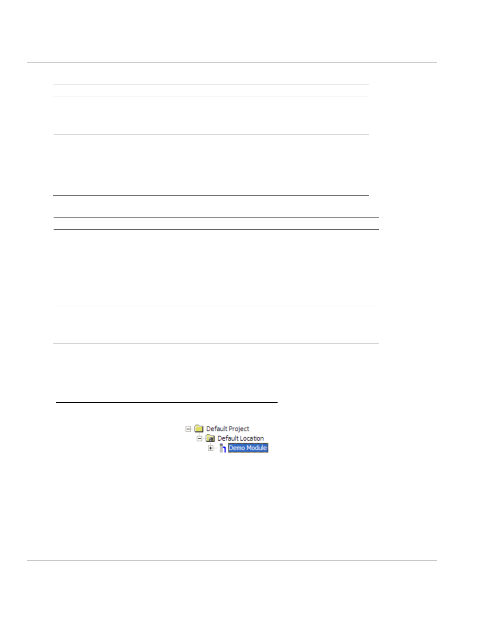
Using ProSoft Configuration Builder (PCB) for Diagnostics
4.2.1 Using the Diagnostic Window in ProSoft Configuration Builder
To connect to the module’s Configuration/Debug serial port
1 Start PCB, and then right-click the module icon.