Emerson Series 600T User Manual
Page 151
Installation Drawings
139
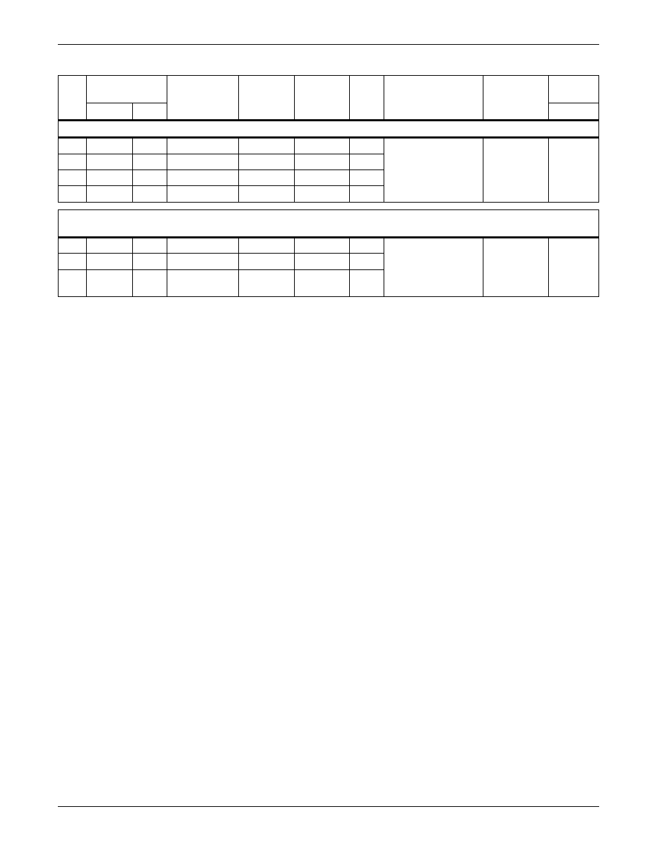
Figure 147 Wiring specifications, Liebert FS and Liebert Series 610
Wire
No.
Terminal
Designation
Signal
Name
Maximum
Voltage
Maximum
Current
Color
Wire Size
& Type
Maximum
Length
Remarks
From
To
Liebert Series 610 UPS - Cable Group #16 (Flywheel CB IFM) From I1 in UPS Module to TB1 on Liebert FS Module
901 I1-TB1-1 TB1-1 Trip Signal (+)
+24 VDC
100mA
1/C #16 (2.5 mm
2
)
Stranded
500 Ft
(150 M
902 I1-TB1-2 TB1-2
Trip Signal (-)
-24 VDC
100mA
903 I1-TB1-7 TB1-7
Aux Comm
24 VDC
100mA
904 I1-TB1-8 TB1-8
Aux N.O.
24 VDC
100mA
Liebert Series 610 UPS - Cable Group #116 Flywheel Aux Power, Customer-Provided to Liebert FS TB1 on Fused
Disconnect
914
FBO
TB1-1
Line
120VAC
3.5A
1/C #16 (2.5 mm
2
)
Stranded
500 Ft
(150m)
UPS-
Protected
Auxiliary
Power
Control
915
FBO
TB1-2
Neutral
120VAC
3.5A
916
FBO
TB1-3
GND
120VAC
3.5A
1. Each cable group must be run in a separate, grounded, rigid metal conduit to prevent control signal interference.
2. Refer to UPS module/Liebert FS control connection diagram for location of wiring connections.
3. All external wires furnished by others.
4. N.O. = Normally Open; N.C. = Normally Closed; Comm = common; F.B.O. = Furnished By Others, GND = ground
5. All wiring must be in accordance with national and local electrical codes.
Dwg. No. Control_WL_S610_Liebert-FS Rev. 01