Figure 153 ups cable entry-bottom, Figure 153 ups cable entry—bottom, Up s – Emerson Series 600T User Manual
Page 157
Installation Drawings
145
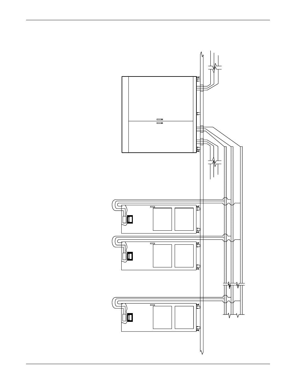
Figure 153 UPS cable entry—bottom
( +
)
B
us
(-
) B
us
Gr
ou
nd
B
u
s
Li
eb
e
rt
F
S
C
abi
ne
t
U
n
it
N
Li
eb
e
rt
FS
Ca
b
in
e
t
Un
it
N
Li
e
b
er
t F
S
Ca
b
in
et
Un
it
N
3-
P
has
e
Ou
tp
ut
UP
S
CA
B
INE
T
3-
P
ha
se
In
p
ut
NOTES
1.
All
ca
bl
es
sho
u
ld
b
e rou
ted
b
efore
bolti
n
g ca
bi
nets t
og
ether.
2.
All Liebert FS cabinets sho
w
n w
ith front do
or o
pen.
3.
Cabine
ts
show
n connected as
one s
ystem.
W
h
en
con
n
ected
to a U
P
S
mo
du
le
, a
ll pow
er
and control wiring supplied by
custom
er (standard)
or Liebert (o
ption).
4.
See installation,
operatio
n and
ma
int
en
ance manua
l f
or ad
di
tiona
l in
formati
on.
5.
All
ex
tern
al
w
iri
ng
is
to
be in
accordance with nation
al
a
n
d loca
l el
ectri
cal codes.
6.
Bus wi
rin
g must be capa
bl
e of ha
ndl
ing
total
lo
ad current.
7.
Power connection must be connected with
a bus structure or to
a
single
point
conn
ect
ion at the UPS (Do not da
isy-
cha
in)
.