Figure 59 read only level parameter view screen, Figure 61 help screen for user setup parameters, Transition setup – Emerson Series 600T User Manual
Page 72
Operation
60
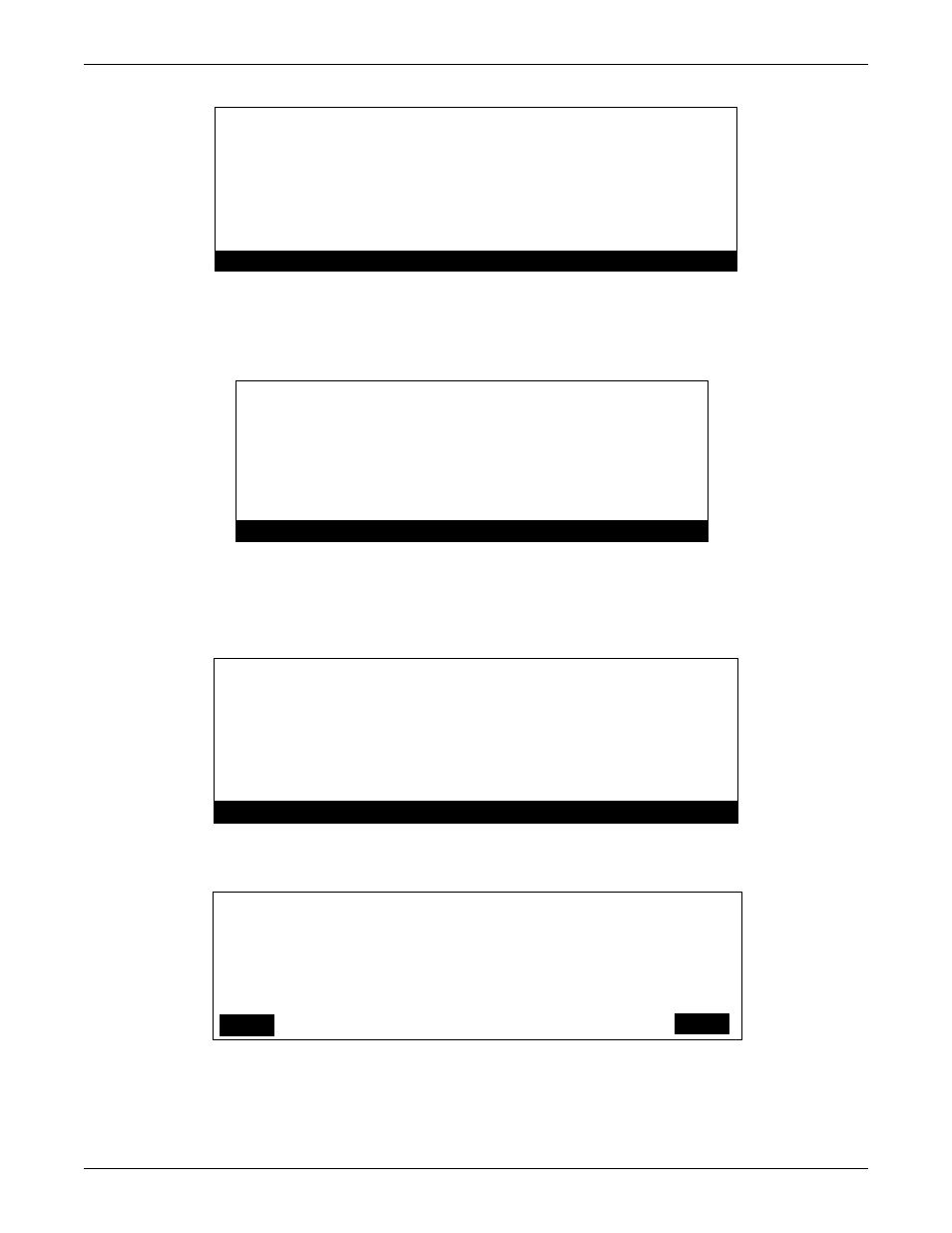
Figure 59 READ ONLY level parameter view screen
In the USER mode, below the 7 basic parameters can be modified, see 6.3.2 - Password for access
level and passwords. Pressing the corresponding number to the parameter to the left of the number
will take you to the parameter setup screen for that particular parameter.
Figure 60 USER level or above parameter edit screen
In setting the parameters there is a help screen to guide the user through the setup and help visualize
the operation the system when utilizing this parameter. The help screens are displayed in
Figures 61 and 62. The help screen also describes the other system parameters used in operation.
Figure 61 HELP screen for User Setup Parameters
Figure 62 Graphical HELP screen for VREG DELTA1, VREG TSOC, and VREG DELTA2 Transition setup
(Pressing the “MORE” button, F1, from Figure 5-8. accesses this screen)
>>
>>
>>
>>
>>
>>
>>
V_CHARGE SETPOINT
V_REG SETPOINT
MAX CHARGE CURRENT
CHARGE AMPS/VOLT
V_REG_DELTA 1
V_REG_DELTA TRANSITION SOC
V_REG_DELTA 2
520 V
500 V
30.0
A
2.0 A
0 V
0%
0 V
/V
HELP
DONE
1.
2.
3.
4.
5.
6.
7.
V_CHARGE SETPOINT
V_REG SETPOINT
MAX CHARGE CURRENT
CHARGE AMPS/VOLT
V_REG_DELTA 1
V_REG_DELTA TRANSITION SOC
V_REG_DELTA 2
520 V
500 V
30.0
2.0 A
0 V
0 %
0 V
/V
HELP
DONE
When voltage is above [1] V_CHARGE
Flywheel charges up and draws :
(( Vbus – [1] V_CHARGE) * [4] AMPS/VOLT) amps,
Not exceeding [3] MAX CHARGE CURRENT.
When voltage sags, it is regulated at
[2] V_REG whose slope can be adjusted by
[5] DELTA 1, [6] SOC TRANS, & [7] DELTA 2
DONE
MORE
DONE
[2]V_REG******-------------------------
|
|
|
|
|
|
******
******-------------
|
|
|
**
**---------
|
---------------------+----+
V
O
L
T
100%
[7]TSOC 0%
[5]DELTA1
[6]DELTA2
PREV
DONE