Emerson Series 600T User Manual
Page 150
Installation Drawings
138
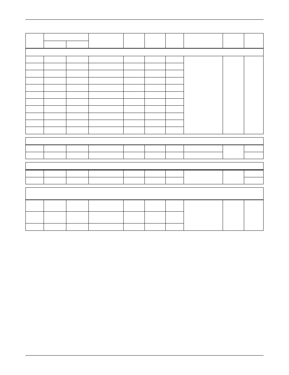
Figure 146 Wiring specifications, Liebert FS and Liebert Npower
Wire
No.
Terminal Designation
Signal
Name
Maximum
Voltage
Maximum
Current
Color
Wire Size
& Type
Maximum
Length Remarks
From
To
Liebert N-Power UPS - Cable Group # 17 (Flywheel CB IFM) From TB69 in UPS Module to TB1 on Liebert FS Module
101
TB69-1
TB1-1
Trip Signal (+)
+24 VDC
100mA
1/C #16 (2.5 mm
2
)
Stranded
1/C #16 (2.5 mm
2
)
Stranded
500 ft
(150m)
102
TB69-2
TB1-2
Trip Signal (-)
-24 VDC
100mA
103
TB69-3
TB1-3
Motor Op Relay
24 VDC
100mA
104
TB69-4
TB1-4
Motor Op On
24 VDC
100mA
105
TB69-5
TB1-5
Motor Op Off
24 VDC
100mA
106
TB69-6
TB1-6
Aux N.O.
24 VDC
100mA
107
TB69-7
TB1-7
Aux Comm
24 VDC
100mA
108
TB69-8
TB1-8
Aux N.C.
24 VDC
100mA
109
TB69-9
TB1-9
Comm
24 VDC
100mA
110
TB69-10
TB1-10
Battery Sense (+) +24 VDC
100mA
112
TB69-12
TB1-11
Battery Sense (-) -24 VDC
100mA
Liebert N-Power UPS - Cable Group # 18 (Flywheel CB IFM) from TB73 in UPS Module to TB6 on Liebert FS Module
Line
TB73-1
TB6-1
Motor Op Pwr
120 VAC
100mA
500 FT
(150m)
Neutral
TB73-2
TB6-2
Motor Op Neutral
N
100mA
Liebert N-Power UPS - Cable Group # 19 (Flywheel CB IFM) From TB70 in UPS Module to TB7 on Liebert FS Module
113
TB70-1
TB7-1
Temp Sensor
24 VDC
100mA
1/C #16 (2.5 mm
2
)
Stranded
500 ft
(150m)
114
TB70-2
TB7-2
Sensor Return
24 VDC
100mA
Liebert N-Power UPS - Cable Group # 116 Flywheel Aux Power, Customer Provided to Liebert FS TB1 on Fused
Disconnect
Output
A PHS
FBO
TB1-1
Line
120VAC
3.5A
1/C #16 (2.5 mm
2
)
Stranded
500 ft
(150m)
UPS-
Protected
Auxiliary
Control
Power
Output
Net
FBO
TB1-2
Neutral
120VAC
3.5A
Gnd
FBO
TB1-3
GND
120VAC
3.5A
1. Each cable group must be run in a separate grounded rigid metal conduit to prevent control signal interference.
2. Refer to UPS module/Liebert FS control connection diagram for location of wiring connections.
3. All external wires furnished by others.
4. N.O. = Normally Open; N.C. = Normally Closed; Comm = common; F.B.O. = Furnished By Others, GND = ground
5. All wiring must be in accordance with national and local electrical codes.
Dwg. No. Control_WL_NPower_Liebert-FS Rev. 1