With liebert ups module – Emerson Series 600T User Manual
Page 142
Installation Drawings
130
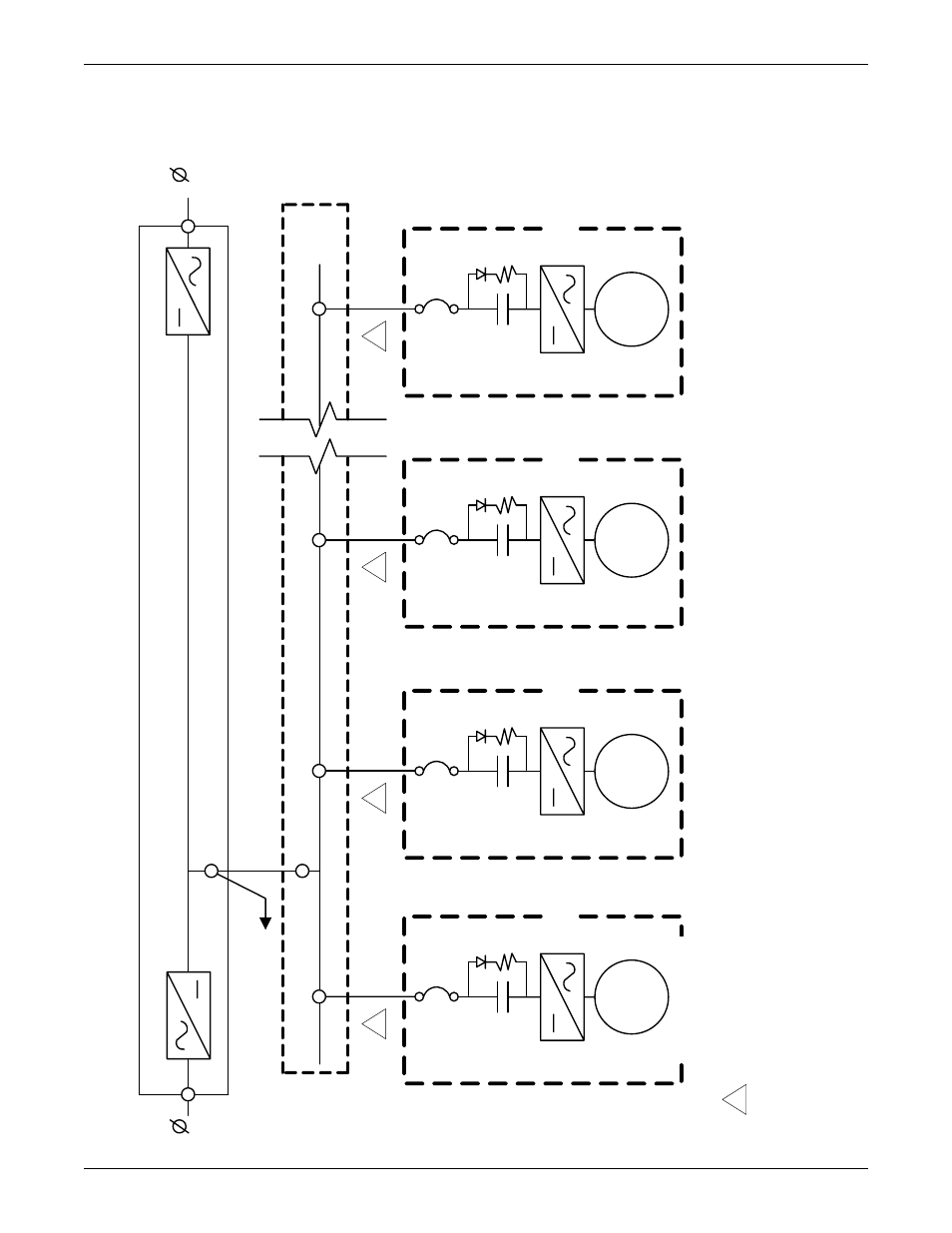
Figure 138One-line diagram—Liebert FS systems with factory-integrated circuit breakers with Liebert UPS
module
B
i-D
ire
ct
ion
al
P
owe
r Co
nv
e
rte
r
NO
T
E
S
1.
N
pow
er
: 2-
8 un
its
in
par
al
le
l w
ithout r
eq
ui
ring a
D
C
di
sc
onnec
t s
w
itc
h.
2.
S
er
ies
610/600 2-
3 uni
ts
in
par
al
le
l w
ith
out
r
equi
ring
a D
C
di
sc
onnec
t s
w
itc
h.
It
c
an
pow
er
a t
otal
o
f t
hr
ee U
V
R
s
max
imum
in
any
c
om
bi
nat
ion of
F
S
uni
ts
, pl
us
modul
e
bat
ter
y di
sc
onnec
t s
w
itc
hes
.
Li
eb
er
t F
S
Sy
st
e
m
s
in
P
a
ra
lle
l
3
Ou
t
Li
eb
er
t U
P
S
M
odu
le
Wh
en p
ar
a
llel
, al
l D
C
pow
er
c
a
bl
es
mu
st
b
e id
e
nt
ic
a
l in
le
ng
th
, ±
1
0%
1
Li
eber
t F
S
(N
)
In
ve
rt
er
Re
ct
ifi
er
D
C
J
unc
tion
B
ox
B
att
er
y/
U
sage
(o
pti
onal
)
12-
10
01
20-
17
Re
v.
0
1
3
In
FL
Y
W
H
E
E
L
No
rm
ally
Op
e
n
C
ir
cui
t B
reak
e
r
1
Bi
-D
ir
ec
tio
na
l
Po
w
e
r C
o
nv
e
rt
er
Li
eber
t F
S
(
3)
F
LYW
H
E
EL
No
rm
a
lly
Op
e
n
Cir
cu
it B
re
a
ke
r
1
B
i-
D
ire
ct
iona
l
P
o
we
r Co
n
ve
rt
er
Li
eber
t F
S
(2
)
FL
Y
W
H
E
E
L
No
rm
ally
Op
en
Cir
cu
it B
re
ak
e
r
1
B
i-D
ire
ct
ion
al
P
owe
r Co
nv
e
rte
r
Li
eber
t F
S
(
1)
F
LYW
H
E
EL
No
rm
ally
Op
en
Cir
cu
it B
re
ak
e
r
1