7installation, 1 preparations for installation – KACO blueplanet gridsave eco 5.0 TR1 User Manual
Page 20
Installation
Page 20
Operating instructions for blueplanet-gridsave eco_EN
Authorised electrician
Installing the device
1. Mark the positions of the drill holes using the cut-outs in the mounting plate.
NOTE: The minimum clearances between two devices, or the device and the ceiling/floor have already been
taken into account in the diagram.
2. Fix mounting plate to the wall with the supplied mounting fixtures.
Make sure that the mounting plate is oriented correctly.
3. Hang the device on the mounting plate using the suspension brackets on the back of the housing.
4. Fix the device into position using the transport bolt supplied.
»
The device is installed. Continue with the installation.
NOTE
An installation carried out and approved by specialist company authorised and certified by KACO
offers you the advantage of an extended warranty for the device.
7
Installation
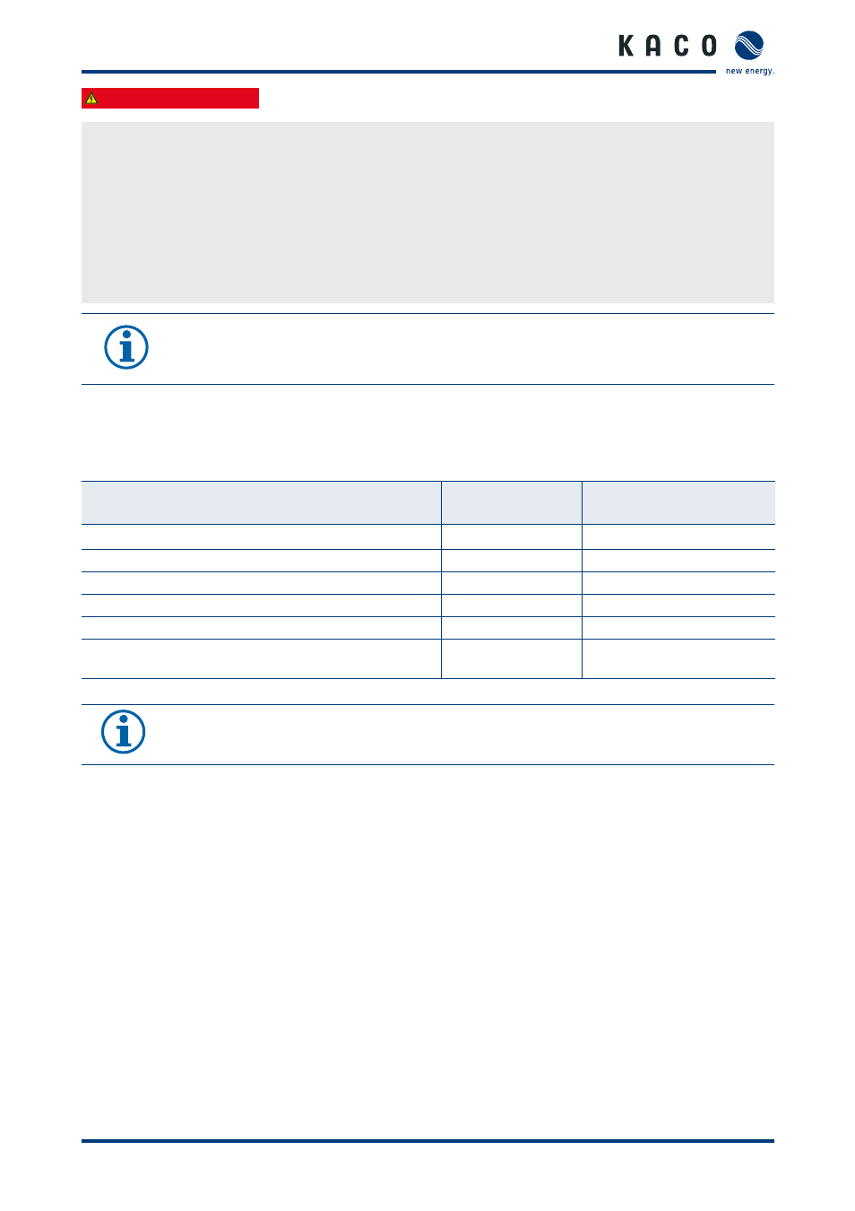
7.1
Preparations for installation
Line cross-sections for connection terminals
Cable cross-sec-
tion
Length of insulation to be
stripped off
AC-source
6 - 16 mm²
16 mm
AC-load
6 - 16 mm²
16 mm
Battery (B+, B-)
50 - 70 mm²
20 mm
Precharge B+,B-,Mid
0.75 - 2.5 mm²
12 mm
External C.T.
0.5 - 2.5 mm²
12 mm
I/O card (digital inputs/outputs, changeover contacts, 12V
power supply)
0.25 - 0.75 mm²
12 mm
Table 3:
Line cross-sections/tightening torque for connection terminal
NOTE
Use copper wires for all electrical connections. (With wire sleeves if required)
During connection work, ensure that no insulation is trapped and/or stuck.