KACO blueplanet gridsave eco 5.0 TR1 User Manual
Page 19
Installation and startup
Operating instructions for blueplanet-gridsave eco_EN
Page 19
Authorised electrician
Key
1
Cover plate
4
Lower lead-through board
2
Terminal cover and expansion card
5
Rear lead-through board
3
Transport bolt
Access to connection area
1. Place the device on its back.
2. Remove the cover plate by unfastening both Torx M5 fastening screws.
3. Unfasten the terminal cover and expansion card using a T15-Torx screwdriver and place to the side.
4. Unfasten and remove the transport bolt underneath the rear lead-through board using a T20-Torx screwdriver.
5. If necessary, also unfasten and remove the lower lead-through board for easier access to the connection ter-
minals. Note: The side screws only need to be unfastened slightly.
»
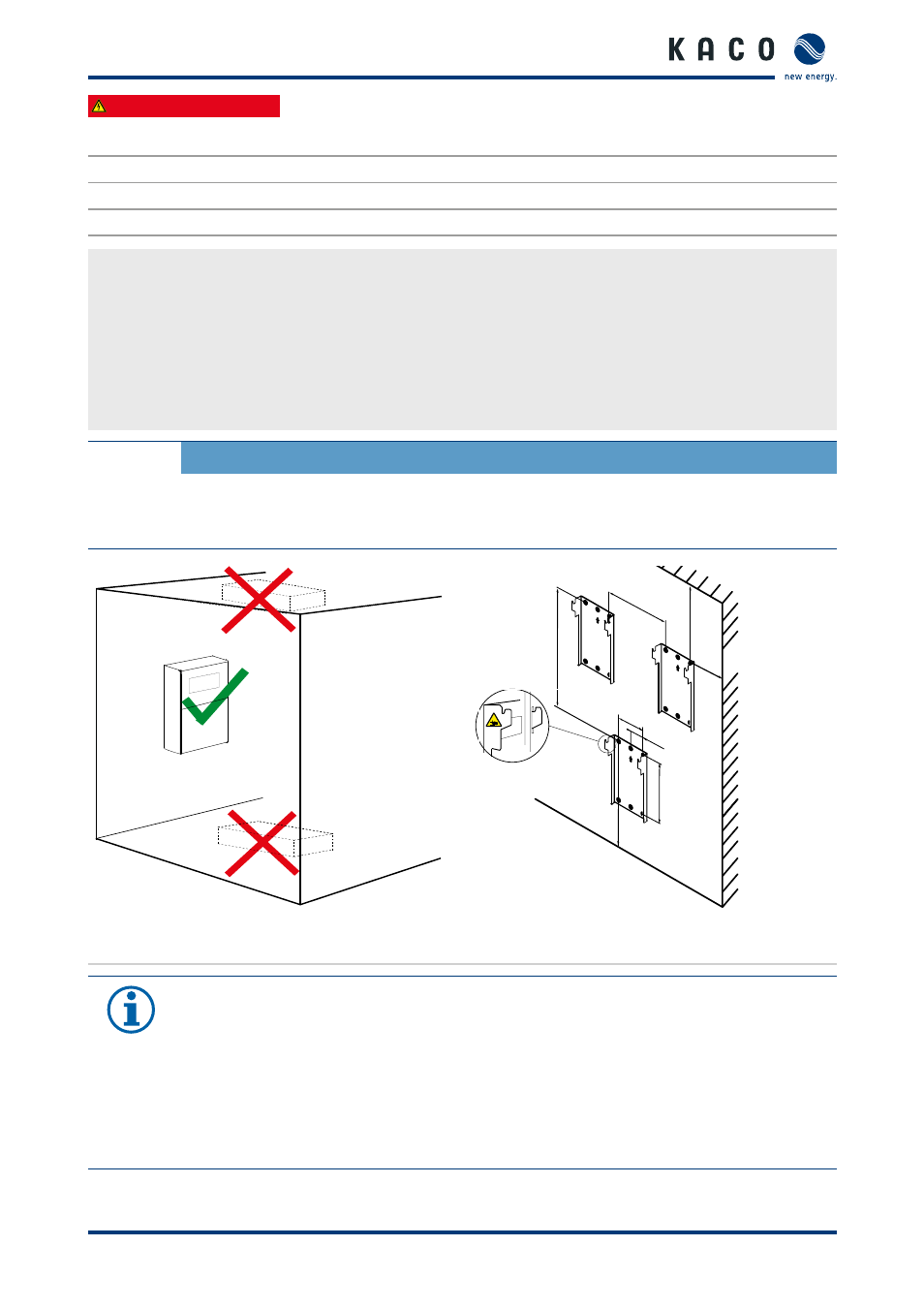
Fit onto the wall.
CAUTION
Use suitable mounting parts.
›
Use the fixing materials supplied or other suitable materials.
›
Only install the device in an upright position
741mm
284mm
282mm
707mm
240mm
120mm
310mm
217mm
Figure 7: Instructions for wall mounting
Figure 8: Wall installation with minimum distances
NOTE
Power reduction due to heat accumulation.
If the recommended minimum clearances are not observed, the device can go into power regulation
mode or protective shutdown due to insufficient ventilation and the resulting heat buildup, and its
rated power will no longer be available.
›
Maintain minimum clearances.
›
An offset according the device width is necessary if one devices is installed above the other.
›
Ensure sufficient heat dissipation.