KACO XP83U-H6 (Canada) User Manual
Page 40
Page 40
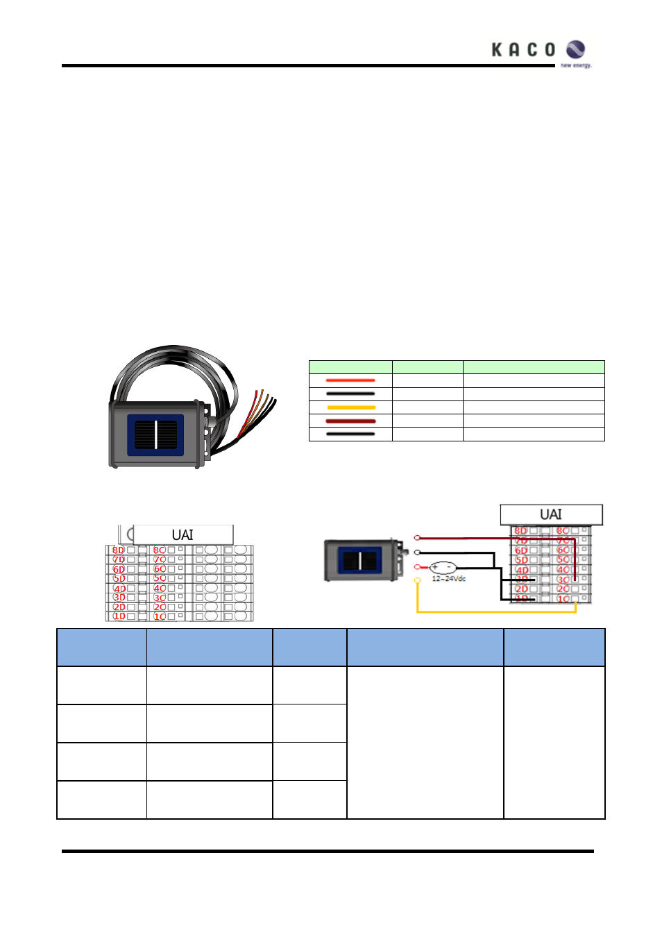
UAI terminal blocks (User Analog Inputs)
The Inverter provides 4 user analog input interface connections and 4 extra terminal blocks are provided as
well for further uses. The User analog inputs are connected to an Irradiation sensor, a PV cell temperature
sensor, and a PT1000 temperature sensor and a Wind Speed sensor. The user analog input interface
voltage range is 0 ~ 10V. The terminal block diagrams depicted below are representative of inverters with the
optional 24VDC power supply. If the inverter does not have the optional power supply, the wire numbers
should be used to identify the proper connections for the sensors.
Note: On some inverters the exact location of the wires in the terminal blocks may vary. Please verify the
wire number in the given charts.
Irradiance and Cell temperature Sensor (Si-12TC)
Si-12TC figure
Wire description
Wire
Color
Specification
Red
VCC(12~24Vdc)
Black
GND
Yellow
Irradiation value(0-10V)
Brown
Cell Temperature(0-10V)
Black
Frame GND
Target port figure
Connect the wires
Port num.
Port name
Wire #
Specification
Wire size
1C
IVP(Yellow)
C311
0V ~ 10Vdc
18-24 AWG
(18-24 AWG㎟)
1D
IVN(Black)
C310
3C
CTP(Brown)
C312
3D
CTN(Black)
C313