KACO XP83U-H6 (Canada) User Manual
Page 38
Page 38
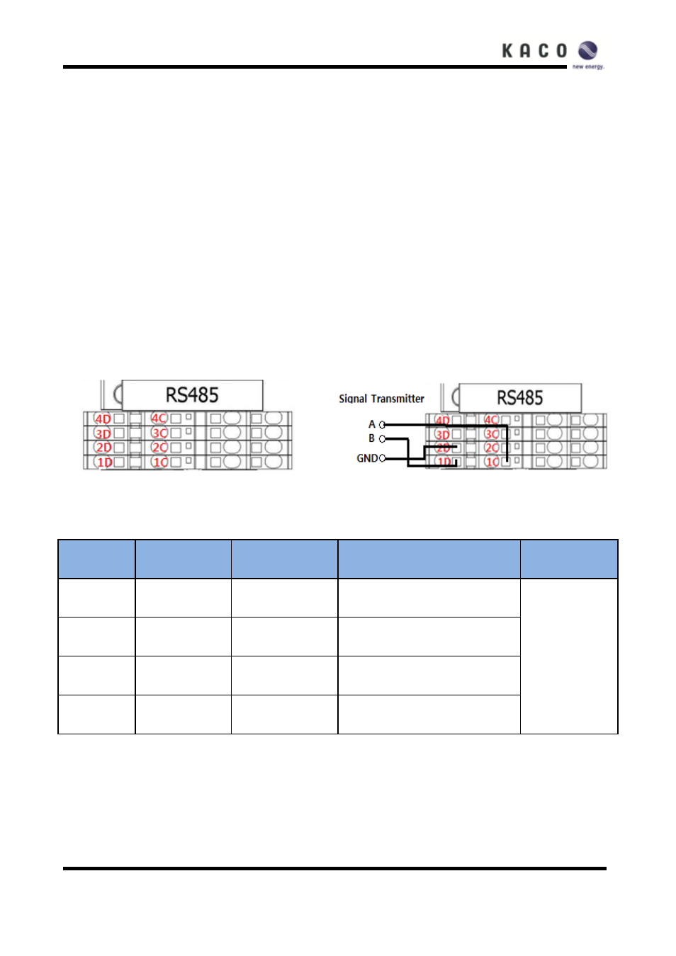
RS 485 terminal blocks
The Inverter provides two RS485 interfaces. RS485-1 communicates with the control board (XCU) and is
reserved
for future use. RS485-2 communicates with the GUI and is used for standard datalogger monitoring. The
connection method for each RS 485 port is detailed below.
Note: Not all RS485 systems use the A and B signals in the same way thereby reversing the polarity. On
some
applications, if there is no communication, reversing the polarity will allow communication.
Note: On some inverters the exact location of the wires in the terminal blocks may vary. Please verify the
wire
number in the given charts.
RS485-1 (Future Use) connections
Target port figure
Connect the wires
▶ To add termination resistance, a jumper should be connected between
1D
and
2C
.
Port num.
Port name
Wire #
Specification
Wire size
1C
RS485A1
C322
RS485 signal A1
18-24 AWG
(0.82-0.20㎟)
1D
RS485B1
C323
RS485 signal B1
2C
RS485C1
C324
Termination resistance setup port
2D
RS485G1
C325
RS485 communication GND1
Note: Termination resistance should only be used at the beginning and the end of the
RS485 chain.