8confi guration and operation, 1 controls – KACO blueplanet 5.0 - 9.0 TL3 User Manual
Page 29
EN
Configuration and Operation
Operating Manual KACO blueplanet 5.0TL3 - 9.0TL3
Page 29
Authorised electrician
Switching on the device
↻ The inverter has been mounted and electrically installed.
↻ The PV generator supplies a voltage above the confi gured start voltage.
1.
Connect the grid voltage using the external circuit breakers.
2. Connect the PV generator using the DC isolator switch (0
→ 1).
»
The inverter begins to operate.
»
During the initial start-up: Follow the instructions of the New Connection Wizard.
8
Confi guration and Operation
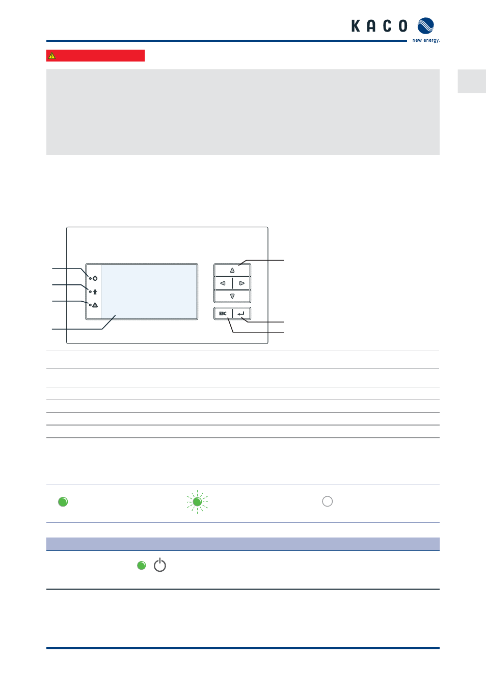
8.1 Controls
The inverter has a backlit LCD as well as three status LEDs. The inverter is operated using six buttons.
1
2
3
4
5
6
7
Figure 31: Control panel
Key
1
"Operating" LED
5
4-way button
2
"Feed-in" LED
6
“OK” button
3
"Fault" LED
7
“ESC” key
4
LCD
8.1.1 LED
indicators
The three LEDs on the front of the inverter show the diff erent operating states.
The LEDs can display the following states:
LED illuminated
LED fl ashing
LED not illuminated
The LED indicators show the following operating status:
Operating status
LEDs
Display
Description
Start
The green "Operating" LED is illuminated
if an AC voltage is present,
(independently of the DC voltage).