8 sealing the connection area, 9 switching on the device – KACO blueplanet 5.0 - 9.0 TL3 User Manual
Page 28
EN
EN
Installation
Page 28
Operating Manual KACO blueplanet 5.0TL3 - 9.0TL3
Authorised electrician
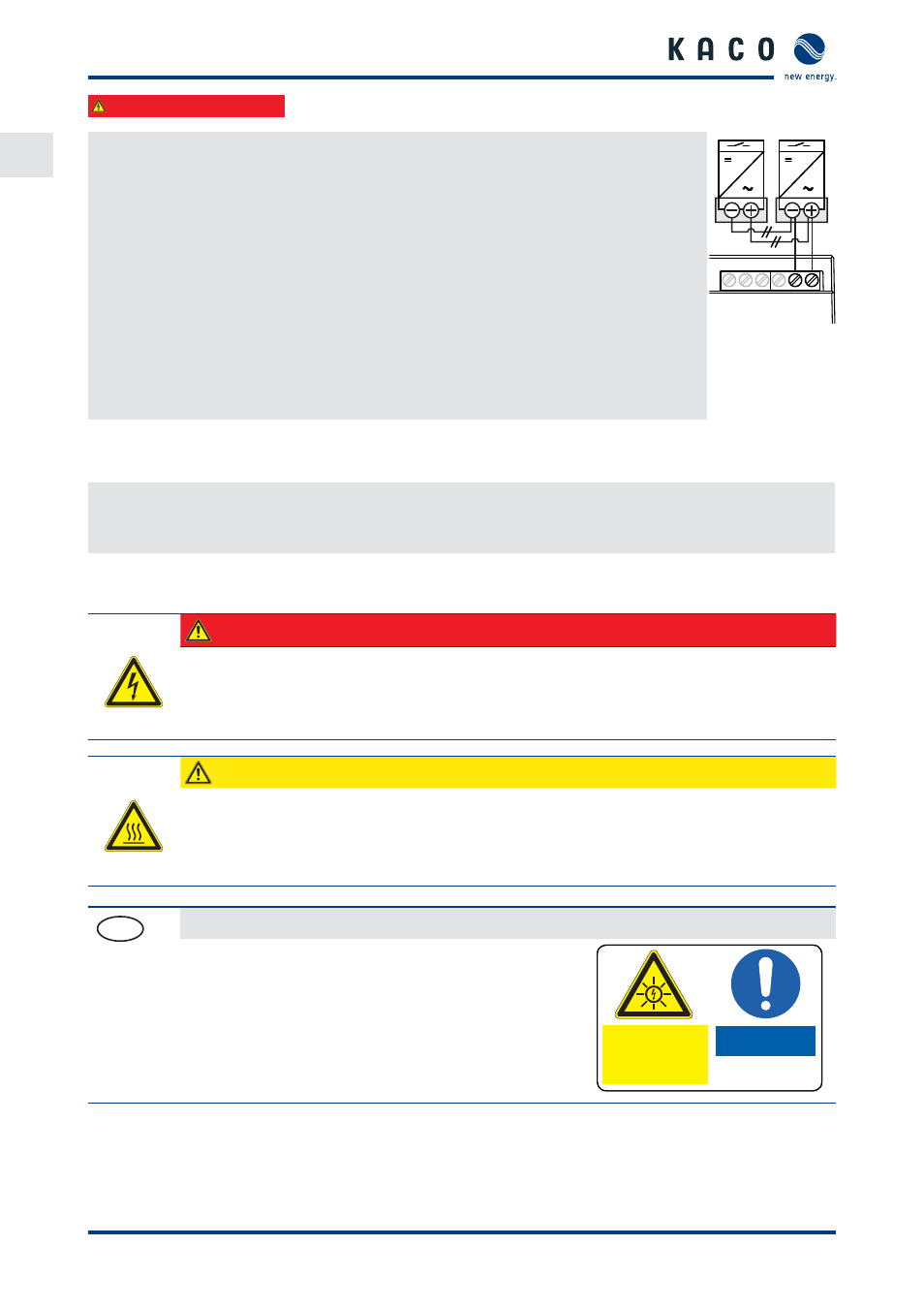
Connecting and activating "Inverter Off " digital input
↻ Can only be used with suitable KACO inverters.
1.
Unscrew the cable fi tting.
2. Thread the connection cables through the cable fi tting.
3. Connect wire A (+) to the terminal marked "INV+" on the fi rst inverter via the "DO1" termi-
nal of the Powador-protect.
4. Connect wire B (-) to the terminal marked "INV-" on the fi rst inverter via the "GND" termi-
nal of the Powador-protect.
5. Connect the other inverters to one another as follows:
–
wire A (+) to wire A (+) and wire B (-) to wire B (-).
6. Tighten the cable fi tting.
7. After commissioning: Activate the support for the Powador protect in the parameter
menu under the "Powador-protect" menu item.
D01
GND
4
3
2
1
Figure 30: Pow-
ador-pro-
tect
7.8
Sealing the connection area
1.
The requirements of protection rating IP65 are met by closing the unused cable fi ttings with blind caps.
2. Place the connection cover on the connection area of the inverter.
3. Screw in the two Torx screws on the front side of the connection cover (blue).
7.9
Switching on the device
DANGER
Lethal voltages are still present in the terminals and cables of the inverter even after the
inverter has been switched off and disconnected.
Severe injuries or death result if the cables and terminals in the inverter are touched.
Only appropriately qualifi ed and authorised electricians may start up the inverter.
CAUTION
Risk of burns from hot housing components.
The housing surface and the heat sink can adopt a surface temperature of 75° in operation.
›
Do not touch the housing surface or heat sink during and immediately after operation.
›
Allow the device to cool down before touching the housing surface.
FR
Attachment of safety label in accordance with UTE C 15-712-1
The code of practice UTE C 15-712-1 requires that, upon connec-
tion to the French low-voltage distribution network, a safety
sticker showing a warning to isolate both power sources when
working on the device must be attached to each inverter.
Attach the provided safety sticker visibly to the outside of
the inverter housing.
ATTENTION
Présence de deux
sources de tension
- Réseau de distribution
-Panneaux photovoltaïques
Isoler les deux sources
avant toute intervention