1 before connecting, 2 maximum generator power, 3 recommended standard connection – KACO blueplanet 5.0 - 9.0 TL3 User Manual
Page 22: Danger
EN
EN
Installation
Page 22
Operating Manual KACO blueplanet 5.0TL3 - 9.0TL3
Authorised electrician
7.5.1 Before
connecting
Ensure that there is no ground fault
1.
Determine the DC voltage and resistance on the PV generator for:
–
protective earth (PE) and positive cable
–
protective earth (PE) and negative cable
If stable voltages can be measured, there is a ground fault in the DC generator or its wiring. The ratio between the
measured voltages gives an indication as to the location of this fault.
In addition, ensure that the PV generator has a total insulation resistance of more than 2.0 MOhm, since the
inverter will not feed in if the insulation resistance is too low.
2. Rectify any faults before connecting the DC generator.
7.5.2
Maximum generator power
The input power of the inverter is limited only by the maximum input current per input. This causes the maximum
input power to increase with the input voltage.
NOTE
The overall power of the unit continues to be limited. If the fi rs input is switched with more than P
max
per MPP tracker, the maximum input power of the second input is reduced.
DANGER
In the expected temperature range of the generator, the values for no-load voltage and short-circuit
current must never exceed the values for U
ocmax
und I
scmax
pursuant to the technical data sheets. (See
Table 1 on page 10)
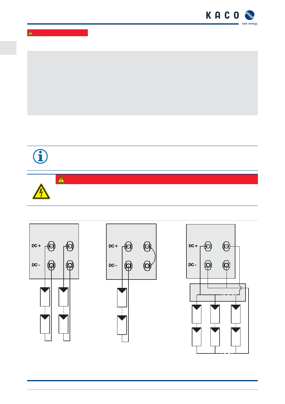
7.5.3
Recommended standard connection
1
Tracker A
2
U
MPP
n
1
n
2
B
1
Tracker A
2
U
MPP
n
1
B
1
Tracker A
2
B
U
MPP
...
n
1
n
2
n
m
=
=
Figure 22: Two generators each on one
MPP tracker
Figure 23: One generator on 1st
tracker, second tracker eac-
tivated
Figure 24: One generator parallel on
both MPP trackers