2 mounting – KACO blueplanet 5.0 - 9.0 TL3 User Manual
Page 16
EN
EN
Mounting
Page 16
Operating Manual KACO blueplanet 5.0TL3 - 9.0TL3
Authorised electrician
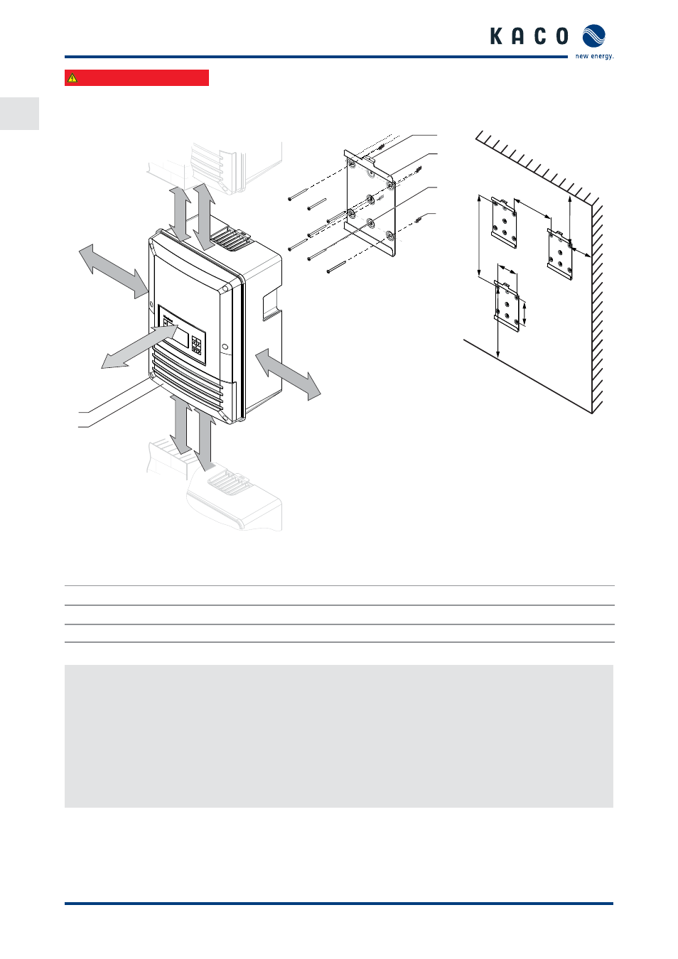
6.2 Mounting
150mm
500 mm
700 mm
250mm
150mm
700 mm
500 mm
1
2
3
4
5
6
1220
510
160
582
920
216
180
Figure 8: Minimum clearances/mounting plate
Key
1
Cover for connection area
4
Mounting plate
2
Screws for mounting (2x Torx)
5
Screws for mounting
3
Suspension bracket
6
Fixings for mounting
Mounting the inverter
1.
Mark the positions of the drill holes using the cut-outs in the mounting plate.
NOTE: The minimum clearances between two inverters, or the inverter and the ceiling/fl oor have already been
taken into account in the diagram.
2. Fix mounting plate to the wall with the supplied mounting fi xtures.
Make sure that the mounting plate is oriented correctly.
3. Hang the inverter on the mounting plate using the suspension brackets on the back of the housing.
4. Fix the inverter with the enclosed screws to the Suspension bracket of the mounting plate.
»
The mounting of the inverter is complete. Continue with the installation.