3 preparing the electrical connection, 4 connect the device to the power grid – KACO blueplanet 5.0 - 9.0 TL3 User Manual
Page 20
EN
EN
Installation
Page 20
Operating Manual KACO blueplanet 5.0TL3 - 9.0TL3
Authorised electrician
NOTE
The permissible bending radius of at least 4x the cable diameter should be observed during installa-
tion. Excessive bending force may negatively impact the protection rating.
All mechanical loads must be absorbed in front of the plug connection.
7.3
Preparing the electrical connection
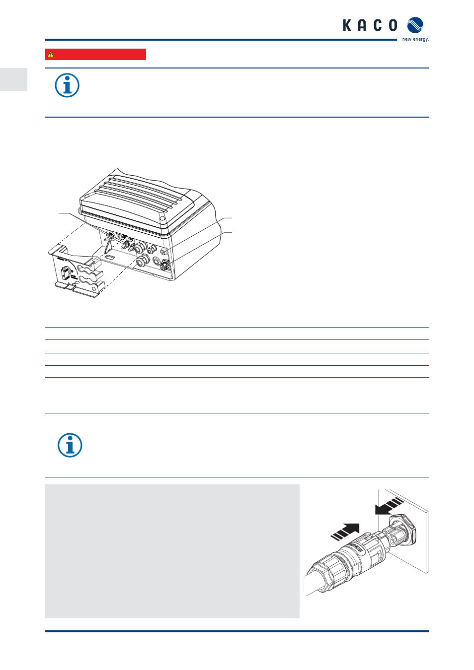
Make the connection for the PV generator as well as the grid connection via the connector at the underside of the
inverter.
1
3
2
Figure 19: Connection area: electrical connection
Key
1
DC connector for PV generator
2
Housing grounding
3
AC connection socket for grid connection
7.4
Connect the device to the power grid
The power connection wires are connected on the right of the connection area (see Figure 19 on page 20).
NOTE
If the cable impedance is high (i.e. long grid-side cables), the voltage at the grid terminals of the
inverter will increase during feed-in to the grid. The inverter monitors this voltage. If it exceeds the
country-specifi c grid overvoltage limit value, the inverter switches off .
›
Ensure that the conductor cross-sections are suffi
ciently large or that the cable lengths are suffi
-
ciently short.
Making the grid connection
↻ AC connector confi gured.
1.
Connect the confi gured plug connectors to the device connector by
fi tting into place.
2. Lay cables correctly.
»
The inverter is now connected to the power grid.
Figure 20: Engage the AC connector
with the device connector.