9 wiring for noise control – Yaskawa MP2000 Series I/O Module User Manual User Manual
Page 98
4.2 Specifications of LIO-06 Module Connections
4.2.9 Wiring for Noise Control
98
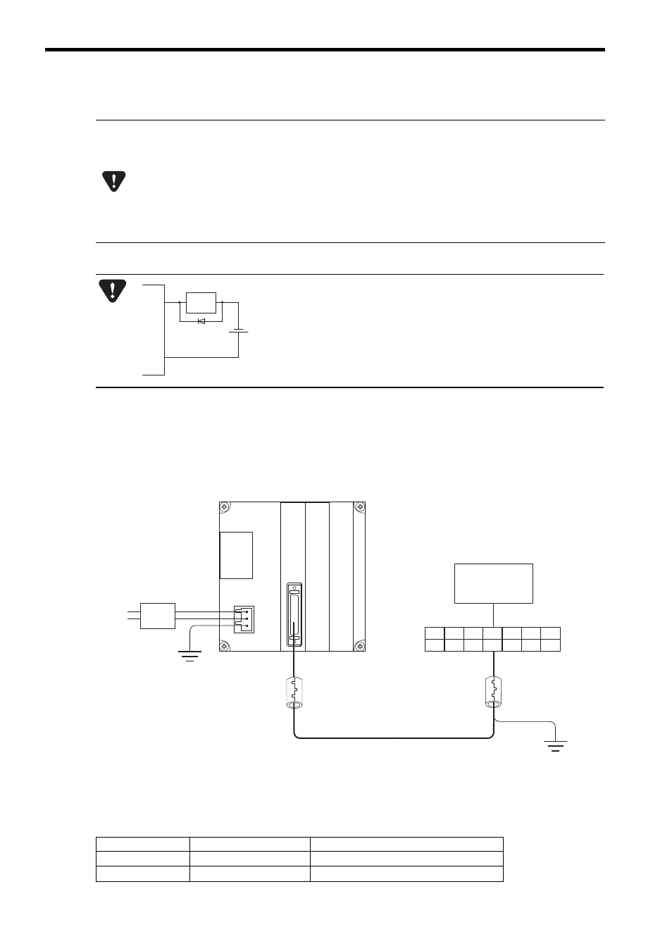
Ground the cable shield between the external devices and the junction-terminal block on the external-device end.
4.2.9 Wiring for Noise Control
When the LIO-06 Module is mounted and used in an environment where there is high-frequency noise from an external
device, the counter may not correctly execute counting. In this case, install a noise filter or a ferrite core to suppress the
high-frequency noise.
The following figure shows an example of installing a noise filter and ferrite cores.
Recommended Parts
A fuse is inserted in the output common line of the LIO-06 Module for circuit protection. However, the fuse
may not be blown out in the cases such as layer shorts in outputs. To ensecure the circuit protection, pro-
vide a protective element such as fuse in each output as shown in the above diagram.
5 V, 12 V, and 24 V are available for phase-Z input voltage.
Note that the pin that is used will differ, depending on the input voltage.
Using the wrong pin may cause an accident.
At 5 V input: Use No.9 pin.
At 12 V input: Use No.34 pin.
At 24 V input: Use No.10 pin.
If you connect an inductive load, connect a diode parallel to the load to
absorb counter electromotive force.
Backward voltage: 10 times the load voltage or greater
Forward current: Load current or greater
OUT
diode
Source circuit
–
+
COM
Inductive
load
LIO-06
MP2000
Series
Machine
Controller
Noise
filter
Power
supply
Terminal
block
External device
Ferrite core
Ferrite core
Name
Model
Manufacturer
Ferrite core
E04SR301334
Seiwa Electric MFG. Co. Ltd.
Noise filter
LF-210N
NEC TOKIN Corporation