5 lio-04 module connections, 1 ) cn1 connector – Yaskawa MP2000 Series I/O Module User Manual User Manual
Page 75
3.2 Specifications of LIO-04/LIO-05 Module Connections
3.2.5 LIO-04 Module Connections
75
3
LIO-04/LIO-05 Module
3.2.5 LIO-04 Module Connections
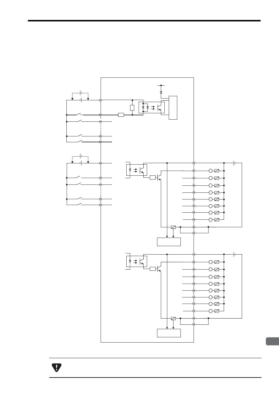
The following diagrams show connection examples for CN1/CN2 connector of the LIO-04 Module.
( 1 ) CN1 Connector
The pins No. 39 and 43 and the pins No. 46 and 50 are internally connected. Connect them externally as well.
2303
JAPMC-IO
+5V
+ -
+
-
+ -
+
-
6
7
32
10
35
1
2
27
5
30
5.6k
ǡ
R
R
38
12
13
41
17
42
16
L
L
L
L
L
+ -
43
37
L
39
15
R
L
L
Fuse blown
detection circuit
45
19
20
48
24
49
23
L
L
L
L
L
+ -
50
44
L
46
22
R
L
L
Input 0
Input 1
Input 6
Input 7
24 VDC
Com-
mon 1
Com-
mon 2
Input 8
Input 9
Input 14
Input 15
CN1 connector
pin No.
Photocoupler
Photocoupler
Photocoupler
Fuse blown
detection circuit
Internal circuit
24 VDC
24 VDC
Output 8
Output 9
Output 10
Output 11
Output 13
Output 14
Output 15
Output 12
Output 1
Output 2
Output 3
Output 5
Output 6
Output 7
Output 4
A fuse is inserted in the output common line of the LIO-04 Module for circuit protection. However, the fuse
may not be blown out in the cases such as layer shorts in outputs. To ensecure the circuit protection, pro-
vide a protective element such as fuse in each output as shown in the above diagram.