Yaskawa MP2000 Series I/O Module User Manual User Manual
Page 118
4.5 Electronic Gear Function
4.5.2 Settings
118
When reference unit is 1
μm:
When 50,000 reference pulses are input, the workpiece will be moved by 50,000
× 1 μm = 50 mm.
4.
Find the load travel distance for each rotation of the load axis using the reference unit and set this dis-
tance to the counter fixed parameter No. 10 (Travel Distance per Machine Rotation).
• Calculation Examples
• For a ball screw pitch of 5 mm and a reference unit of 0.001 mm:
(Reference unit)
5.
Set the Encoder Gear Ratio and the Machine Gear Ratio in the counter fixed parameters No. 11 and
No.12.
When the encoder axis has rotated m times and the mechanical configuration allows the load axis to rotate n
times, set the following values:
No. 11 (Encoder Gear Ratio) = m rotations
No. 12 (Machine Gear Ratio) = n rotations
Setting range: 1 to 65,535 [rotations]
For the configuration shown in the diagram:
Gear ratio = n/m = (3/7)
× (4/9) = 4/21
Therefore, set the following values:
No.11 (Encoder Gear Ratio) = 4 (rotations)
No.12 (Machine Gear Ratio) = 21 (rotations)
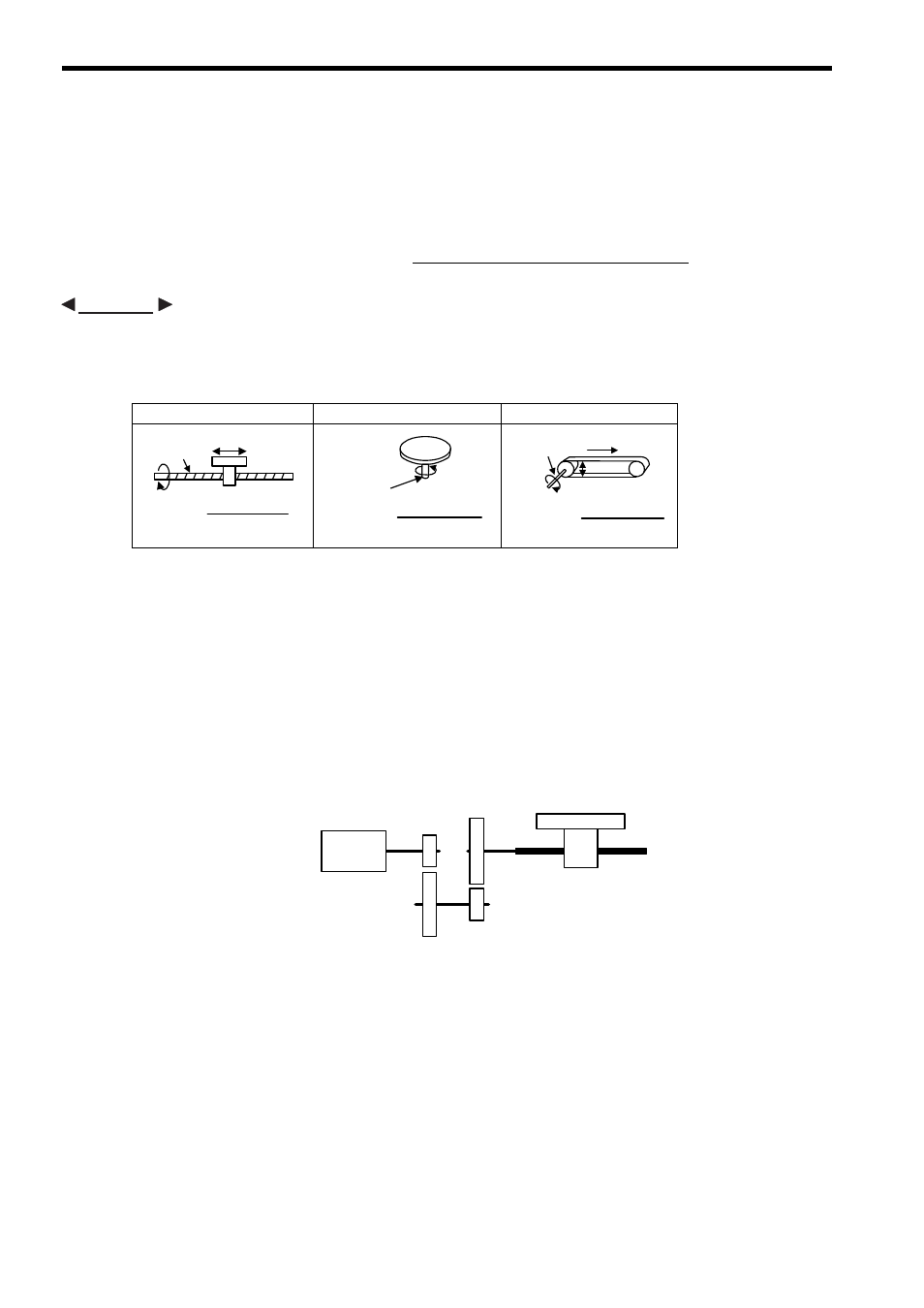
Ball screw
Rotary table
Belt + pulley
Load travel distance per load axis rotation
Reference unit
Load travel distance per rotation
of load axis (reference unit)
=
EXAMPLE
5
0.001
-------------
5000
=
P
One
rotation
P
Reference unit
=
Load axis
P: Pitch
360°
Reference unit
Load axis
One
rotation =
Reference unit
Load axis
D: Pulley diameter
D
π
D
=
π
D
One
rotation
エンコーダ軸
m
回転
7回転
3回転
9回転
4回転
負荷軸
n
回転
Encoder axis
m rotations
7 rotations
4 rotations
9 rotations
3 rotations
Load axis n rotations