4 pi latch function – Yaskawa MP2000 Series I/O Module User Manual User Manual
Page 115
4.4 Details of Counter Functions
4.4.4 PI Latch Function
115
4
LIO-06 Module
4.4.4 PI Latch Function
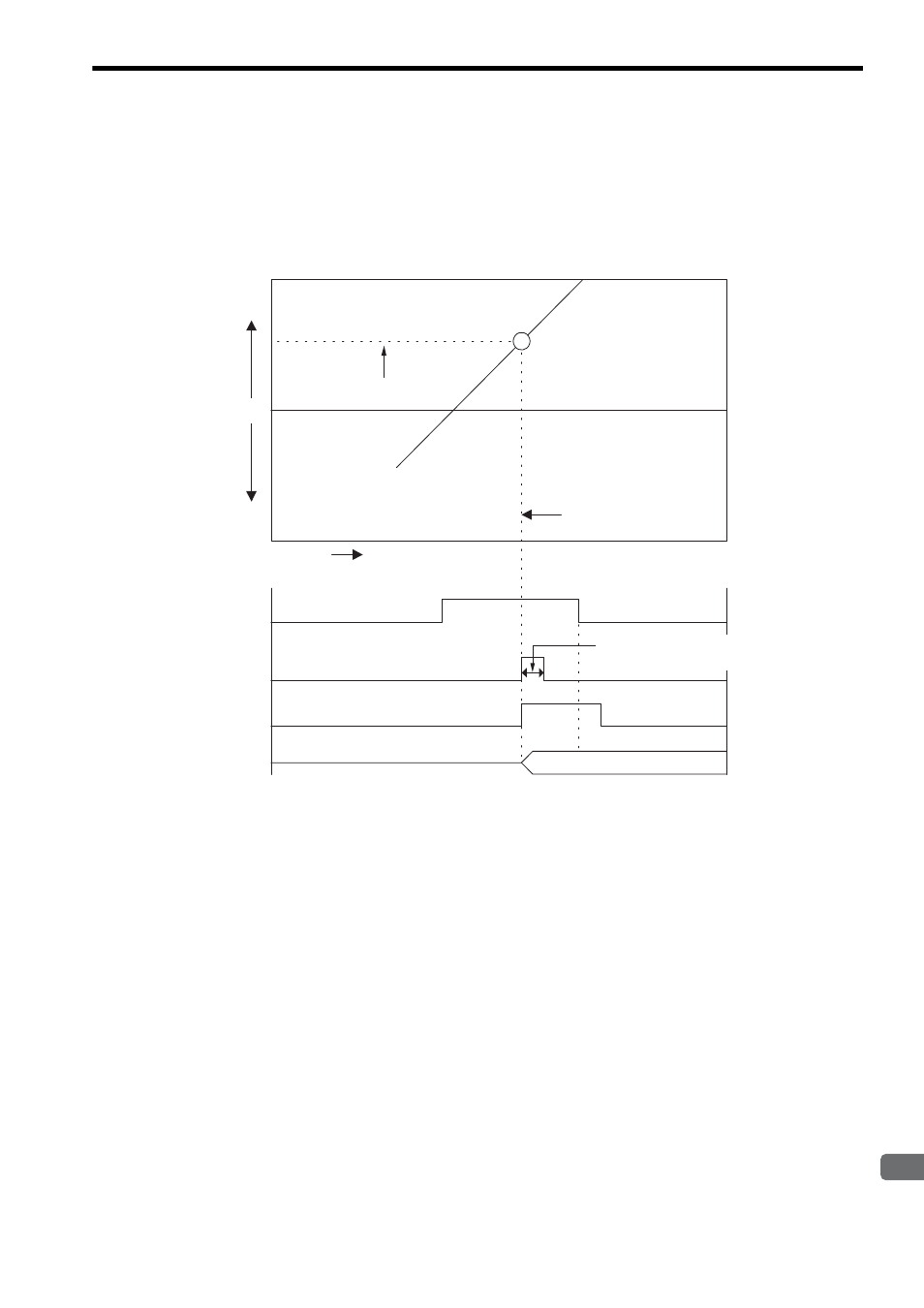
The PI latch function saves (latches) the current value to a memory register (IL
06) on the rising edge of an external
signal.
Select either a discrete input (DI latch) or phase-Z (Z latch) as the external signal.
The following graph shows the number of occurrences from when PI latch signal is output to when the rising edge of
an external signal is detected and PI latch data is displayed.
* 1. When discrete input is changed from ON to OFF, the next ON signal cannot be received unless at least 500
μs
passes after the change.
* 2. At 5-V/12-V input: When phase-Z input is changed from ON to OFF, the next ON signal cannot be received unless
at least 1
μs passes after the change.
At 24-V input: When phase-Z input is changed from ON to OFF, the next ON signal cannot be received unless at
least 2
μs passes after the change.
0
㧔㧗㧕
㧔㧙㧕
DI latch (discrete input): 60
μs or more
*1
Phase C pulse (Phase-Z input): 1
μs or more
*2
Current
counter
value
PI latch completed
signal
External input signal
(either a discrete
signal or phase Z)
PI latch detection
request signal
PI latch register
display
Time (s)
PI latch data
External signal rising edge
detected point
Hardware latch
PINT
㧔PI latch data㧕