8bytes – Yaskawa DeviceNet Option Card CM05x User Manual
Page 89
F7/G7/P7 Assemblies B-7
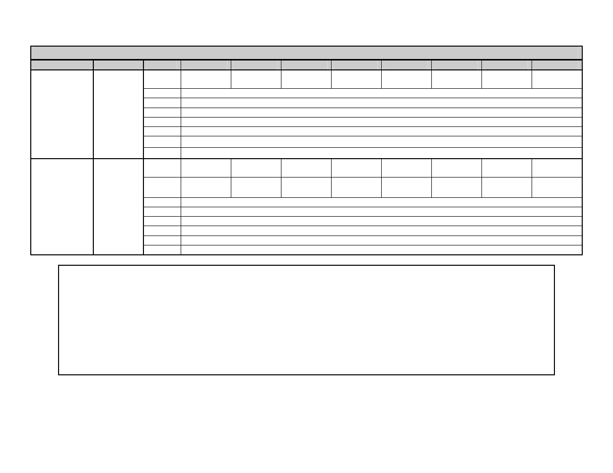
Input Assemblies – Polled Producing Assembly (continued)
Assembly
# of Bytes
Byte
Bit 7
Bit 6
Bit 5
Bit 4
Bit 3
Bit 2
Bit 1
Bit 0
135 *
4
8
bytes
0 Drive
Fault
Drive
Alarm
Drive
Ready
At
Speed
Fault Reset
Active
Drive
Reversing
At Zero
Speed
Running
1
Service Code (Read, Written)
Current
2
Class Number to Read/Written
Status 2
3
Attribute Number to Read/Written
4
Data (Low Byte)
5
Data (High Byte)
6
Output Current in Amps x 100 (Low Byte) *1
7
Output Current in Amps x 100 (High Byte) *1
136 *
4
8
bytes
0 Drive
Fault
Drive
Alarm
Drive
Ready
At
Speed
Fault Reset
Active
Drive
Reversing
At Zero
Speed
Running
1
Zero
Servo
Complete*3
Motor
Selection*3
Term M5-M6
Output *3
Term M3-M4
Output
Term M1-M2
Output
Local/
Remote
During
Ride-Thru
Torque
2
Output Torque % x 10 (Low Byte)
and Speed
3
Output Torque % x 10 (High Byte)
Status
4
Motor Speed in Hz x 100 (Low Byte)
5
Motor Speed in Hz x 100 (High Byte)
6
Speed Reference in Hz x 100 (Low Byte)
7
Speed Reference in Hz x 100 (High Byte)
Notes:
*1 Output Current is given in Amps X 100 (For example 1000 = 10.00 Amps) for models F7U/G7U/P7U -20P4 to -27P5 and -40P4 to -47P5.
Output Current is given in Amps X 10 (For example 100 = 10.0 Amps) for models F7U/G7U/P7U -2011 to -2110 and -4011 to -4300.
This value is based on the drive capacity model.
*2 Speed Reference and Output Speed are given in Hz X 100 (For example 2000 = 20.00 Hz)
*3 F7 and G7 Drives only.
*4 Yaskawa specific Polled Consuming or Polled Producing Assembly.