Option board setup – Yaskawa DeviceNet Option Card CM05x User Manual
Page 18
Setup and Installation 3-3
Option Board Setup
The DeviceNet Option Board requires setup prior to operation. DIP switches must be set prior to the application
of input AC power to the Drive. The states of these DIP switches are read only on power-up.
Option Board DIP Switch Settings
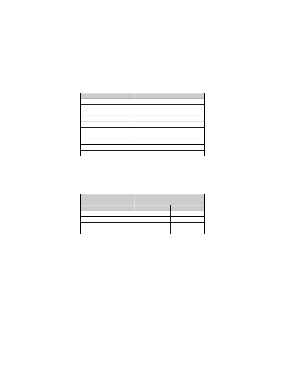
The DIP switches are used to setup DeviceNet network characteristics. The DIP switch functions are defined in
the following table:
DIP Switch Number
Function
1
Baud Rate, Bit 1
2
Baud Rate, Bit 0
3
Node Number, MSB
4 Node
Number
5 Node
Number
6 Node
Number
7 Node
Number
8
Node Number, LSB
9 Not
Used
10
Master Idle Operation
DIP switches 1 and 2 are used to select the baud rate of the DeviceNet network. The baud rate setting of the
Option Board must match the baud rate setting of the rest of the devices on the DeviceNet network. The
available baud rates are defined in the following table. The cable distance between any two points in the cable
system must not exceed the Maximum Cable Distance allowed for the baud rate selected. See Chapter 4 for
information on calculating the Maximum Cable Distance.
DeviceNet
Baud Rate
DIP Switch Position
(KBaud)
Switch 1
Switch 2
125 Off
Off
250 Off
On
On Off
500
On On