Factory recommended branch circuit protection, D.3 ul/cul standards – Yaskawa AC Drive Z1000 User Manual
Page 369

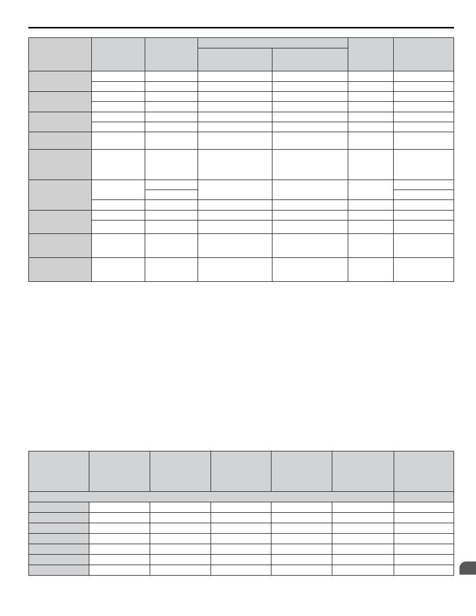
Wire Gauge
Terminal
Screws
Crimp Terminal
Model Number
Tool
Insulation
Cap
Model No.
Code
<1>
Machine No.
Die Jaw
8 mm
2
8 AWG
M4
8-4NS
YA-4
AD-901
TP-008
100-064-249
M5
R8-5
YA-4
AD-901
TP-008
100-054-032
14 mm
2
6 AWG
M5
R14-5
YA-4
AD-902
TP-014
100-054-034
M8
R14-8
YA-5
AD-952
TP-014
100-054-035
22 mm
2
4 AWG
M5
22-5NS
YA-5
AD-953
TP-022
100-051-262
M8
R22-8
YA-5
AD-953
TP-022
100-051-263
30 / 38 mm
2
3 / 2 AWG
M8
R38-8
YA-5
AD-954
TP-038
100-051-264
50 / 60 mm
2
1 AWG
1/0 AWG
1/0 AWG × 2P
M8
R60-8
YA-5
AD-955
TP-060
100-051-265
70 mm
2
2/0 AWG
2/0 AWG × 2P
M8
CB70-S8
YF-1 YET-300-1
TD-322,TD-311
TP-080
100-064-417
70-8
100-064-250
M10
70-10
YF-1 YET-300-1
TD-322,TD-311
TP-080
100-064-251
80 mm
2
3/0 AWG × 2P
3/0 AWG × 4P
M10
80-10
YF-1 YET-300-1
TD-323,TD-312
TP-080
100-051-267
M12
80-L12
YF-1 YET-300-1
TD-323,TD-312
TP-080
100-051-558
100 mm
2
4/0 AWG × 2P
4/0 AWG × 4P
M12
100-L12
YF-1 YET-300-1
TD-324,TD-312
TP-100
100-051-560
150 mm
2
250 kcmil × 2P
300 kcmil × 2P
M12
150-L12
YF-1 YET-300-1
TD-325,TD-313
TP-150
100-051-562
<1> Codes refer to a set of three crimp terminals and three insulation caps. Prepare input and output wiring using two sets for each connection.
Example 1: Models with 300 kcmil for both input and output require one set for input terminals and one set for output terminals, so the user should
order two sets of [100-051-272].
Example 2: Models with 4/0 AWG × 2P for both input and output require two sets for input terminals and two sets for output terminals, so the user
should order four sets of [100-051-560].
Note:
Use crimp insulated terminals or insulated shrink tubing for wiring connections. Wires should have a continuous maximum allowable
temperature of 75 °C 600 Vac UL-approved vinyl-sheathed insulation.
n
Factory Recommended Branch Circuit Protection
WARNING! Fire Hazard. Install adequate branch circuit protection according to applicable local codes and this manual. Failure to comply
could result in fire and damage to the drive or injury to personnel. The device is suitable for use on a circuit capable of delivering not more
than 100,000 RMS symmetrical amperes, 240 Vac (200 V class) and 480 Vac (400 V class), when protected by branch circuit protection
devices specified in this manual.
Branch circuit protection shall be provided by any of the following: Non-time delay Class J, T, or CC fuses sized at 300% of the drive input
rating, or Time delay Class J, T, or CC fuses sized at 175% of the drive input rating, or MCCB sized at 200% maximum of the drive input
rating.
Yaskawa recommends installing one of the following types of branch circuit protection to maintain compliance with UL508C.
Table D.4 Factory Recommended Z1000 AC Drive Branch Circuit Protection
Model
Nominal Output
Power (HP)
AC Drive Input
(A)
MCCB Rating (A)
<1>
Time Delay Fuse
Rating (A)
<2>
Non-time Delay
Fuse Rating (A)
<3>
Bussmann
Semiconductor
Fuse Model
(Fuse Ampere)
<4>
Three-Phase 200 V Class
2A0011
3
10.6
20
17.5
30
FWH-40B (40)
2A0017
5
16.7
30
25
50
FWH-50B (50)
2A0024
7.5
24.2
40
40
70
FWH-80B (80)
2A0031
10
30.8
60
50
90
FWH-100B (100)
2A0046
15
46.2
90
80
125
FWH-150B (150)
2A0059
20
59.4
110
100
175
FWH-175B (175)
2A0075
25
74.8
150
125
200
FWH-225A (225)
D.3 UL/cUL Standards
YASKAWA ELECTRIC TOEP C710616 45E YASKAWA AC Drive – Z1000 User Manual
369
D
Standards Compliance
