Refer to, For details on using this function, D2-03: master speed reference lower limit – Yaskawa AC Drive Z1000 User Manual
Page 170
No.
Parameter Name
Setting Range
Default
d1-01 to d1-04
Frequency Reference 1 to 4
0.00 to 240.00 Hz
<1>
<2>
0.00 Hz
<2>
d1-16
Frequency Reference 16
0.00 to 240.00 Hz
<1>
<2>
0.00 Hz
<2>
d1-17
Jog Frequency Reference
0.00 to 240.00 Hz
<1>
<2>
6.00 Hz
<2>
<1> The upper limit is determined by the maximum output frequency (E1-04) and upper limit for the frequency reference (d2-01).
<2> Setting units are determined by parameter o1-03. The default is “Hz” (o1-03 = 0).
Multi-Step Speed Selection
To use several speed references for a multi-step speed sequence, set the H1-oo parameters to 3 and 4. To assign the Jog
reference to a digital input, set H1-oo to 6.
Notes on using analog inputs as Multi-Speed 1 and 2:
• The first frequency reference (Multi-Speed 1) comes from the source specified in b1-01. When using an analog input terminal
to supply the frequency reference, assign the frequency reference source to the control terminals (b1-01 = 1).
• When an analog input is set to “Auxiliary frequency 1” (H3-02 or H2-06 = 2), the value set to this input will be used as the
Multi-Step Speed 2 instead of the value set to parameter d1-02. If no analog inputs are set for “Auxiliary frequency 1”, then
d1-02 becomes the reference for Multi-Step Speed 2.
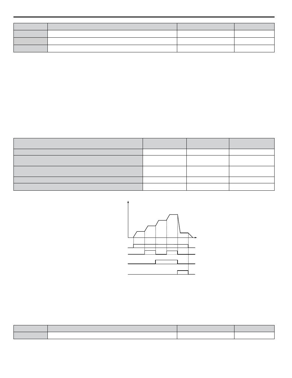
Select the different speed references as shown in
illustrates the multi-step speed selection.
Table 4.24 Multi-Step Speed Reference and Terminal Switch Combinations
Reference
Multi-Step Speed
H1-oo = 3
Multi-Step Speed 2
H1-oo = 4
Jog Reference
H1-oo = 6
Frequency Reference 1 (set in b1-01)
OFF
OFF
OFF
Frequency Reference 2
(d1-02 or input terminal A1, A2)
ON
OFF
OFF
Frequency Reference 3
(d1-03 or input terminal A1, A2)
OFF
ON
OFF
Frequency Reference 4 (d1-04)
ON
ON
OFF
Jog Frequency Reference (d1-17)
<1>
−
−
ON
<1> The Jog frequency overrides all other frequency references.
d1-04
d1-17
ON
ON
ON
ON
ON
Multi-step Speed Ref. 2
Jog Reference
Time
Multi-step Speed Ref. 1
Frequency
reference
d1-01
(A1)
d1-02
(A2)
d1-03
FWD (REV) Run/Stop
Figure 4.32 Preset Reference Timing Diagram
n
d2-03: Master Speed Reference Lower Limit
Sets a lower limit as a percentage of the maximum output frequency that will only affect a frequency reference entered from
the analog input terminals (A1 or A2) as the master speed reference. This is unlike parameter d2-02, which affects all frequency
references regardless of their source.
Note:
When lower limits are set to both parameters d2-02 and d2-03, the drive uses the greater of those two values as the lower limit.
No.
Parameter Name
Setting Range
Default
d2-03
Master Speed Reference Lower Limit
0.0 to 110.0%
0.0%
4.13 Advanced Drive Setup Adjustments
170
YASKAWA ELECTRIC TOEP C710616 45E YASKAWA AC Drive – Z1000 User Manual