Yaskawa AC Drive Z1000 User Manual
Page 179
Setting 1: Enter command not necessary
Parameter value changes become effective immediately without the need to send an Enter command.
n
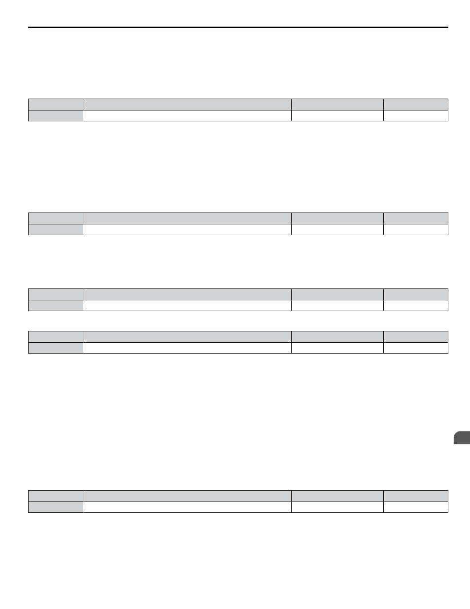
H5-12: Run Command Method Selection
Selects the type of sequence used when the Run command source is set to MEMOBUS/Modbus communications
(b1-02, b1-16 = 2).
No.
Name
Setting Range
Default
H5-12
Run Command Method Selection
0 or 1
0
Setting 0: FWD/Stop, REV/Stop
Setting bit 0 of MEMOBUS/Modbus register 0001H will start and stop the drive in the forward direction. Setting bit 1 will
start and stop the drive in reverse.
Setting 1: Run/Stop, FWD/REV
Setting bit 0 of MEMOBUS/Modbus register 0001H will start and stop the drive. Setting bit 1 changes the direction.
n
L5-02: Auto Restart Fault Output Operation Selection
Determines if a fault output is triggered (H2-oo = E) when the drive attempts to restart.
No.
Name
Setting Range
Default
L5-02
Auto Restart Fault Output Operation Selection
0, 1
0
Setting 0: No Fault Output
Setting 1: Fault Output Is Set
n
L5-04: Fault Reset Interval Time
Determines the amount of time to wait between restart attempts when parameter L5-05 is set to 1.
No.
Name
Setting Range
Default
L5-04
Fault Reset Interval Time
0.5 to 600.0 s
10.0 s
n
L5-05: Fault Reset Operation Selection
No.
Name
Setting Range
Default
L5-05
Fault Reset Operation Selection
0, 1
1
Setting 0: Count Successful Restarts
The drive will continuously attempt to restart. If it restarts successfully, the restart counter is increased. This operation is
repeated each time a fault occurs until the counter reaches the value set to L5-01.
Setting 1: Count Restart Attempts
The drive will attempt to restart using the time interval set to parameter L5-04. A record is kept of the number of attempts to
restart to the drive, regardless of whether those attempts were successful. When the number of attempted restarts exceeds the
value set to L5-01, the drive stops attempting to restart.
n
L6-13: Motor Underload Protection Selection
Sets Motor Underload Protection (UL6) based on motor load and determines whether the level of L6-02 refers to fbase or
fmax.
Selects the operation of underload detection UL6. Underload is detected when the output current falls below the underload
detection level defined by L6-14 and L2-02.
No.
Name
Setting Range
Default
L6-13
Motor Underload Protection Selection
0, 1
0
4.13 Advanced Drive Setup Adjustments
YASKAWA ELECTRIC TOEP C710616 45E YASKAWA AC Drive – Z1000 User Manual
179
4
Start-Up Programming & Operation