6 connection of the pv modules, Connection at positive grounding – SMA SC 500HE-US Installation User Manual
Page 62
8 Electrical Connection
SMA America, LLC
62
SC500HEUS-IA-US_en-14
Installation Manual
8.6 Connection of the PV Modules
Do not connect the PV modules until the optional communication cables have been connected
(see section 7). DC distribution boxes (e.g. Sunny Central String-Monitor) must be installed between
the PV modules and the Sunny Central, where the PV module cables are gathered and led to the
Sunny Central.
The Photovoltaic System Grounding must be installed per the requirements of Sections 690.41
through 690.47 of the National Electrical Code, ANSI/NFPA 70 and is the responsibility of the
installer.
8.6.1 PV Modules: DC − Connection at Negative Grounding and
DC+ Connection at Positive Grounding
Connection with Terminal Blocks
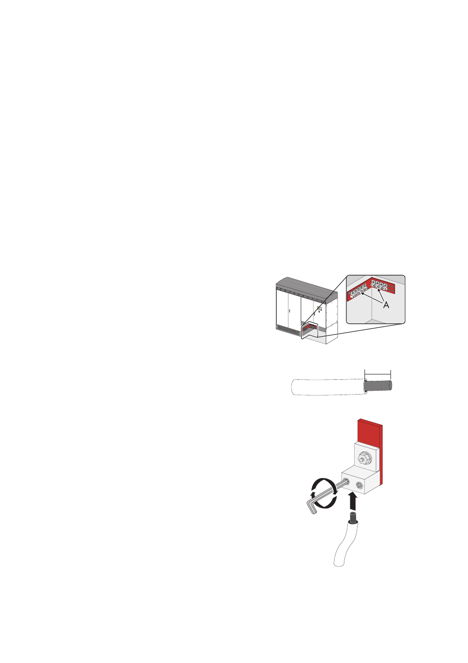
The illustration below shows a Sunny Central which is equipped for connection to 9 or 18 DC strings.
1. Strip the cable by about 1.2 in. (30 mm).
2. Open the screw terminal completely.
3. Plug the copper inner conductor of the cable into
the screw terminal.
4. Tighten the screw terminal using a screwdriver.
The required torque is 315 in-lb.
5. Connect all grounded DC path cables of the PV
modules as described above.
A
Screw terminals for the connection of the PV modules'
grounded DC path cables.
1.2 in.