2 attach the sunny central to the base – SMA SC 500HE-US Installation User Manual
Page 35
SMA America, LLC
5 Transport and Installation
Installation Manual
SC500HEUS-IA-US_en-14
35
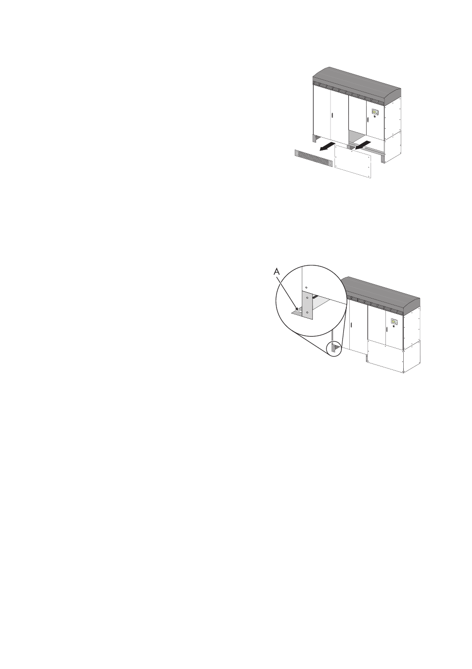
2. Remove the kick plates of the Power Cabinet by
pulling them toward you (see figure on the right).
3. Remove the kick plates of the Control Cabinet
carefully by pulling it 3 to 4 in. toward you.
Pay attention not to tear the grounding-cable.
4. Remove the grounding-cables on the backside of
the kick plates.
5. Remove the kick plates of the Control Cabinet.
6. Load the cabinet on a forklift or a crane fork from
the front (see section 5.3.2).
7. Transport the cabinet to the installation site. During transport, be sure to follow all the instructions
provided in section 5.3).
5.5.2 Attach the Sunny Central to the base
The mounting holes (A) are located on the outside of the
Sunny Central's stands.
The holes for mounting the Sunny Central to the base
have a diameter of 0.63 in. (16 mm). Use appropriate
mounting material.
Figure to the right: Mounting hole in the front left stand of
the Power Cabinet.
1. Insert screws in all 6 mounting holes of the
Sunny Central (for the position of the mounting
holes, refer to section 5.2).
2. Tighten screws.