4 identifying the sunny central, 5 firmware, 4 identifying the sunny central 3.5 firmware – SMA SC 500HE-US Installation User Manual
Page 20
3 The Sunny Central
SMA America, LLC
20
SC500HEUS-IA-US_en-14
Installation Manual
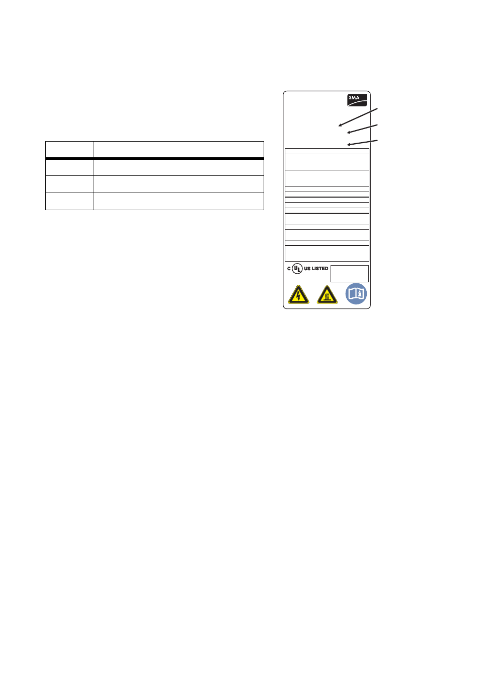
3.4 Identifying the Sunny Central
You can identify the Sunny Central using the type plate
(see figure at right). The type plate is on the inside of the
Control and Interface Cabinet on the upper left side and
in the Power Cabinet on the right side.
3.5 Firmware
The Sunny Central's firmware, and that of the display, are shown on the display of the Sunny Central.
The Sunny Central’s user manual describes how to obtain the firmware version.
Position
Description
A
Type description of the Sunny Central
B
Serial number of the Sunny Central
C
Date of manufacture
SMA America
www.sma-america.com
SUNNY CENTRAL
Model:
xxxxxxxxxxxxxxxxxxx
SC500HE-US
Serial No.: xxxxxxxxx
Fabrication Date:
Max. Continuous output Power*
Operating voltage range (Vac 3-Phase)*
Min
xxx
Operating frequency range (Hz)*
Max. continuous output current*
Range of input operating voltage
MPPT Range of operating DC voltage*
xxxkWac
Nominal
Max
xxx
xxx
Min
xx.x
Nominal
Max
xx.x
xx.x
xxx.xAac
Output power factor
x.xx
xxx - xxx Vdc
The unit contains DC-Ground and Fault Detector
and Interruptor
Max. operating current*
xxx - xxx Vdc
xxx Adc
ENCLOSURE
Type 3R (IP54)
*For more details and for tightening torque,
allowable wire size and type see the Operator’s
Manual
xx/xxxx
A
Fabrication Version: xxx
Utility interactive inverter
LISTED UL 1741 36AN
Range of input operating voltage
xxx - xxx Vdc
Range of input operating voltage
xxx - xxx Vdc
Engineered in Germany - Assembled in Denver/Colorado
US80
B
C