SMA SC 500HE-US Installation User Manual
Page 25
SMA America, LLC
5 Transport and Installation
Installation Manual
SC500HEUS-IA-US_en-14
25
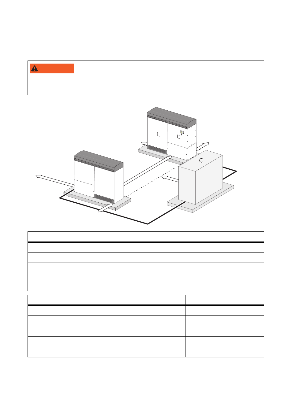
Minimum Clearance 2 Sunny Centrals with Transformer
Observe the specified minimum clearances for the cables, for ventilation and for opening the doors.
8"3/*/(
Opening the doors of two Sunny Central devices blocks the escape route.
• Only open the doors of one Sunny Central at the same time.
Position
Description
A
Sunny Central 1
B
Sunny Central 2
C
Medium voltage transformer
D
Cable route between Sunny Central and transformer. The cables between the
Sunny Central and the transformer may not be longer then 49 ft. (15 m).
Position
Dimensions
Sunny Central rear
12 in. (300 mm)
Distance between Sunny Central A an B
48 in. (1,800 mm)
Right side of Sunny Central A
47 in. (1,200 mm)
Left side of Sunny Central B
6 in. (150 mm)
Distance between transformer and Sunny Centrals
47 in. (1,200 mm)
12 in.
(300 mm)
6 in.
48 in.
47 in.
A
B
D
D
(150 mm)
(1220 mm)
(1200 mm)
47 in.
(1200 mm)
12 in.
(300 mm)