6 attaching the conduits – SMA SC 500HE-US Installation User Manual
Page 37
SMA America, LLC
6 Attaching the Conduits
Installation Manual
SC500HEUS-IA-US_en-14
37
6 Attaching the Conduits
In this section you will learn where to insert the cables in the Sunny Central and where to punch the
holes for the conduits.
The DC cables, the AC cables and the communication cables can be routed into the Sunny Central's
Control and Interface Cabinet from the right or from below. The two options are described below.
6.1 Insert cables from the right into the Sunny Central
Insert the DC cables, the AC cables and the data cables into the Sunny Central from the right. A metal
sheet is attached to the Sunny Central for this purpose.
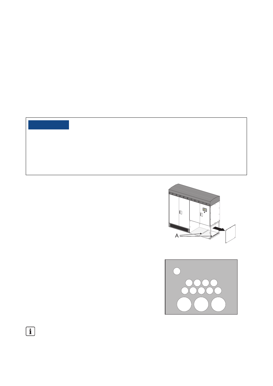
1. Remove the plate screws.
2. Put the screws and washers aside.
3. Remove the kick plate of the Control Cabinet
carefully by pulling it 3 to 4 in. toward you. Pay
attention not to tear the grounding-cable.
4. Remove the grounding-cable on the backside of the
kick plate of the Control Cabinet.
5. Remove the kick plate of the Control Cabinet.
6. Remove the braces (A).
7. Mark all the holes for the conduits.
Example for a plate prepared for the connection of
9 DC strings.
A: Conduit for AC cable
B: Conduit for DC cable
C: Conduit for communication cable
/05*$&
Seeping moisture during installation of the Sunny Central.
Damage to the electronics of the Sunny Central.
• Do not open the Sunny Central when it is raining or when a high humidity is present (> 95%).
• For conduit hubs, use only UL Listed rainproof, or wet location hubs complying with UL 514B
for entry into the enclosure.
Do not lay the AC connection cables of one phase together in one cable duct. All
cables of one phase must have the same length.
Please refer to section 8.7.2 for information on arrangement of AC cabling.
A
A
A
C
B B B B
B
B
B
B
B