3 additional earthing of the enclosure, 4 connecting the pv array (dc), 1 conditions for dc connection – SMA SB 2500TL-21 Installation User Manual
Page 35: Additional earthing of the enclosure, Connecting the pv array (dc), Conditions for dc connection
SMA Solar Technology AG
Electrical Connection
Installation Manual
SB25-30TLST-21-IA-en-13
35
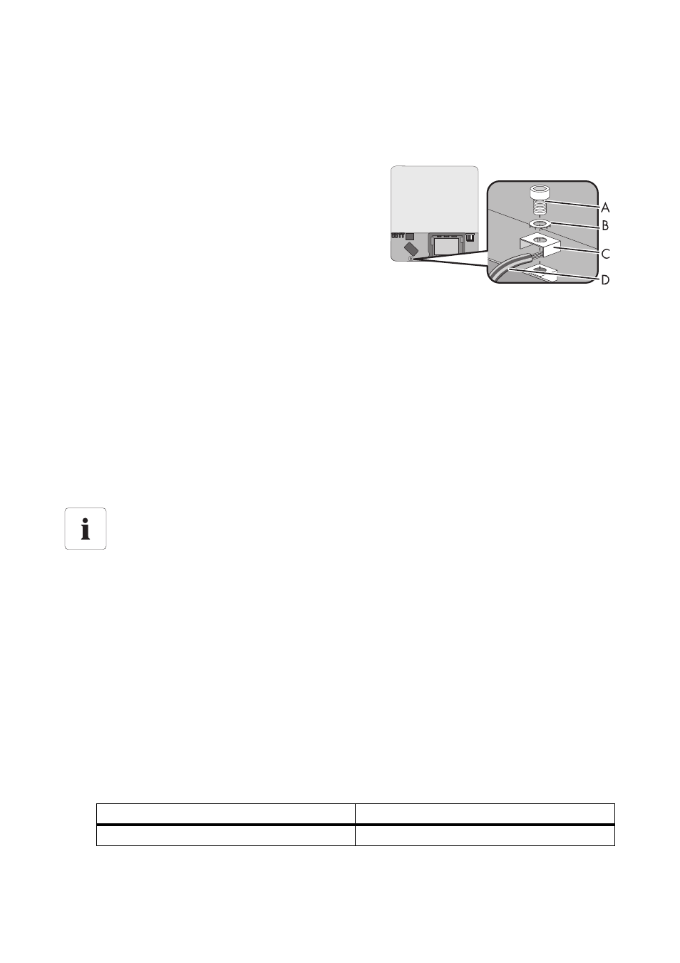
6.3.3 Additional Earthing of the Enclosure
If required in the country of installation, you can use the earth terminal on the enclosure to connect a
second protective conductor or as equipotential bonding.
1. Undo screw (A) half way. Use an Allen key (AF 4)
to do this.
2. Insert the stripped earthing cable (D) under the
clamping bracket (C) (maximum conductor
cross-section 10 mm²).
3. Fasten terminal (C):
– Place the conical spring washer over the screw.
The grooved side of the conical spring washer
must face towards the screw head.
– Tighten the screw (torque: 6 Nm). Use an Allen
key (AF 4) to do this.
☑ The teeth of the conical spring washer press into the clamping bracket. The earthing cable
now has conductive connection to the enclosure.
6.4 Connecting the PV Array (DC)
6.4.1 Conditions for DC Connection
• Requirements for the PV modules of the connected strings:
– same type
– same number of in-series-connected PV modules
– identical alignment
– identical tilt
• The connection cables of the PV modules must be equipped with connectors. The DC connectors
for the DC connection are included in the delivery.
• At the DC input of the inverter, the following limits must not be exceeded:
• On the statistically proven coldest day of the year the open-circuit voltage of the PV array must
never exceed the maximum input voltage of the ivnerter.
Use of Y adaptors
Y adaptors must not be visible or freely accessible within close proximity of the inverter.
• The DC circuit must not be interrupted by Y adaptors.
• Observe the procedure for disconnecting the inverter (see Section 8.2
"Disconnecting the Inverter from Voltage Sources" (page 57)).
Maximum input voltage
Maximum input current
750 V (DC)
15.0 A (DC)