2 symbols on the inverter, Symbols on the inverter – SMA SB 2500TL-21 Installation User Manual
Page 14
Product Description
SMA Solar Technology AG
14
SB25-30TLST-21-IA-en-13
Installation Manual
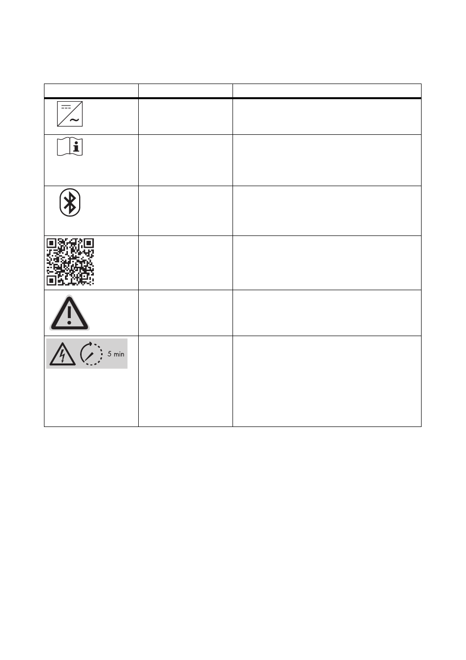
4.2 Symbols on the Inverter
Symbol
Description
Explanation
Inverter
This symbol defines the function of the green LED.
It indicates the operating state of the inverter.
Observe the
documentation.
This symbol defines the function of the red LED.
It indicates a fault or disturbance. Please read the
manual to find information on how to remedy the
fault or disturbance.
Bluetooth
This symbol defines the function of the blue LED.
It indicates that communication via Bluetooth is
activated.
QR Code
®
Links to additional information on the inverter can
be found at www.SMA-Solar.com.
NOTICE, danger!
Observe the connection requirements for a
second protective conductor 6.3.1 "Conditions
for the AC Connection" (page 29).
Danger to life due to
high voltages in the
inverter
The capacitors in the inverter may be charged
with very high voltages.
• Disconnect the inverter from voltage
sources (see Section 8.2) and wait
five minutes before opening the upper lid,
in order to allow time for the capacitors to
discharge.