SMA SB 2500TL-21 Installation User Manual
Page 30
Electrical Connection
SMA Solar Technology AG
30
SB25-30TLST-21-IA-en-13
Installation Manual
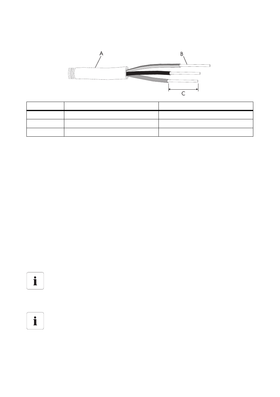
Cable Requirements
Connection of a Second Protective Conductor
The inverter is equipped with a protective conductor monitoring device. This protective conductor
monitoring device detects when there is no protective conductor connected and disconnects the inverter
from the electricity grid if this is the case. Depending on the installation site and earthing system, it may
be advisable to deactivate the protective conductor monitoring. This would apply, for instance, if there
is no neutral conductor and you intend to install the inverter between two line conductors. If you are
uncertain about this, ask your network operator or SMA Solar Technology AG to advise.
• Depending on the earthing system, deactivate the protective conductor monitoring device
• To ensure safety in accordance with IEC 62109 when the protective conductor monitoring is
deactivated, connect a protective conductor to the connecting terminal plate for the AC cable
(minimum cross-section: 10 mm², copper wire).
or
• Connect a second protective conductor with the same cross-section as the original protective
conductor (see Section 6.3.3 "Additional Earthing of the Enclosure" (page 35)). This will
prevent touch current if the original protective conductor fails.
Load Disconnection Unit
Object
Description
Value
A
External diameter
12 mm to 21 mm
B
Conductor cross-section
maximum 10 mm²
C
Stripping length
approx. 12 mm
Connection of a second protective conductor
In some countries a second protective conductor is required as a matter of principle. In
each case, observe the applicable regulations for the site.
Attach the warning labels on the load disconnect unit on the AC side
To prevent arcing, always disconnect the inverter from the AC and DC side before starting
work on the PV array.
Attach the warning label "Risk of burns from electric arc" so that it is clearly visible on the
external AC disconnection device.