HEIDENHAIN iTNC 530 (340 420) User Manual
Page 291
HEIDENHAIN iTNC 530
263
8.3 Cy
cles f
o
r Dr
illing, T
a
pping and Thr
ead Milling
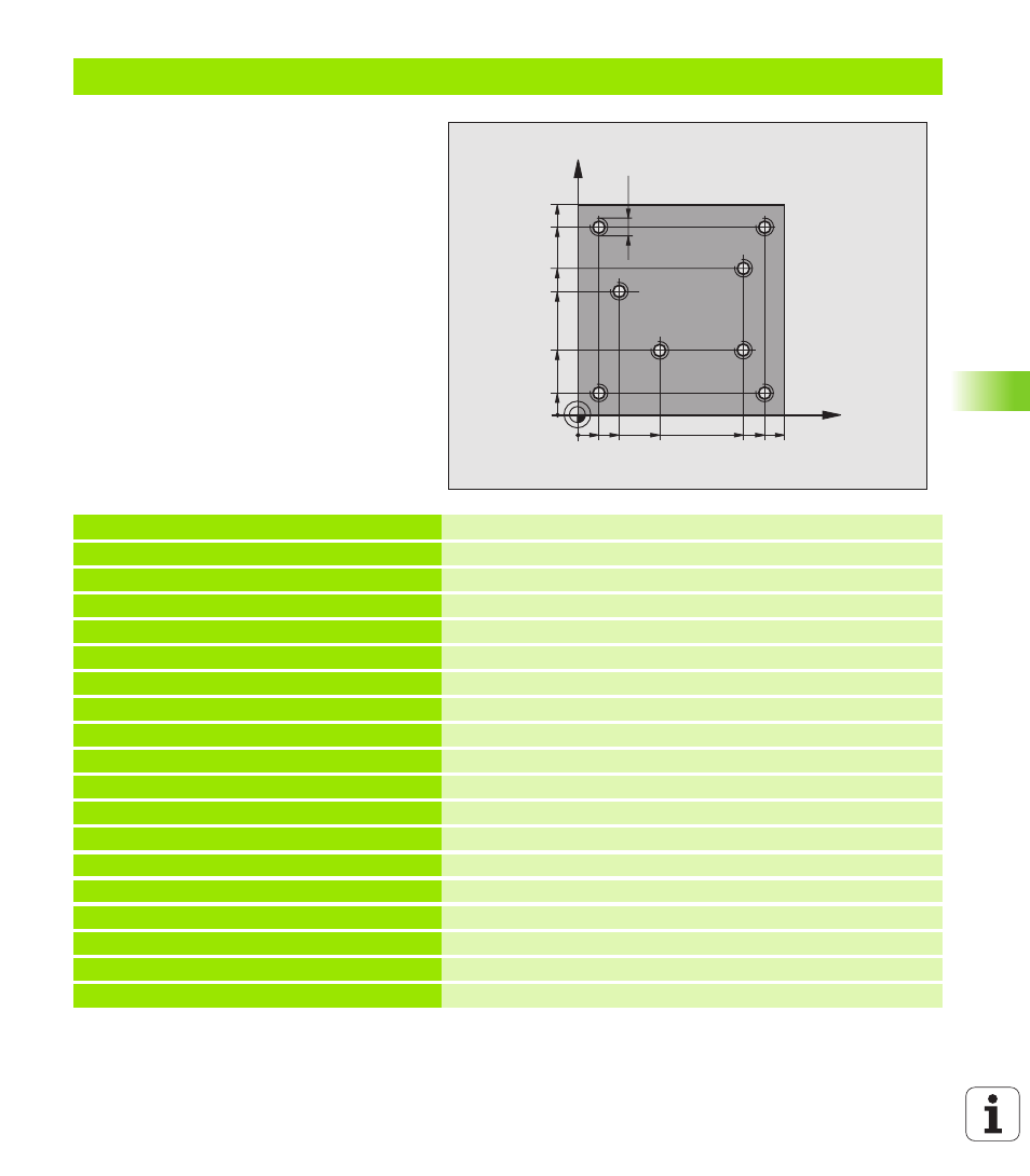
Example: Calling drilling cycles in connection with point tables
The drill hole coordinates are stored in the point
table TAB1.PNT and are called by the TNC with
CYCL CALL PAT
.
The tool radii are selected so that all work steps
can be seen in the test graphics.
Program sequence
n
Centering
n
Drilling
n
Tapping
0 BEGIN PGM 1 MM
1 BLK FORM 0.1 Z X+0 Y+0 Z-20
Define the workpiece blank
2 BLK FORM 0.2 X+100 Y+100 Y+0
3 TOOL DEF 1 L+0 R+4
Tool definition of center drill
4 TOOL DEF 2 L+0 2.4
Define tool: drill
5 TOOL DEF 3 L+0 R+3
Tool definition of tap
6 TOOL CALL 1 Z S5000
Tool call of centering drill
7 L Z+10 RO F5000
Move tool to clearance height (Enter a value for F.
The TNC positions to the clearance height after every cycle
8 SEL PATTERN “TAB1“
Defining point tables
9 CYCL DEF 200 DRILLING
Cycle definition: Centering
Q200=2
;SAFETY CLEARANCE
Q201=-2
;DEPTH
Q206=150
;F FEED RATE FOR PLUNGING
Q202=2
;INFEED DEPTH
Q210=0
;DWELL TIME AT TOP
Q203=+0
;SURFACE COORDINATE
0 must be entered here, effective as defined in point table
Q204=0
;SECOND SET-UP CLEARANCE
0 must be entered here, effective as defined in point table
Q211=0.2
;DWELL TIME AT DEPTH
X
Y
20
10
100
100
10
90
90
80
30
55
40
65
M6