Rs-232-c/v.24 interface – HEIDENHAIN TNC 310 (286 140) User Manual
Page 238
14 Tables and Overviews
226
14.2 Pin La
y
out and Connecting Cable f
or the D
ata Int
erf
ace
14.2 Pin Layout and Connecting Cable
for the Data Interface
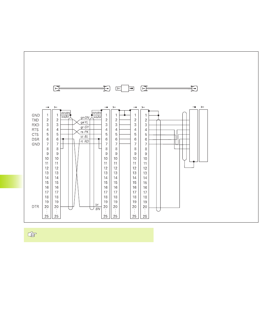
RS-232-C/V.24 Interface
HEIDENHAIN devices
The connector pin layout on the adapter block differs
from that on the TNC logic unit (X21).
Non-HEIDENHAIN devices
The connector pin layout of a non-HEIDENHAIN device may differ
considerably from that of a HEIDENHAIN device.
This often depends on the unit and type of data transfer. The figure
above shows the connector pin layout on the adapter block.
HEIDENHAIN devices
External
device
e.g. FE
HEIDENHAIN
standard cable
3 m
RS-422 Adapter
block
HEIDENHAIN
connecting cable
max. 17 m
X21
TNC
Id.-Nr. 274 545 01
Id.-Nr. 286 998 ..
Id.-Nr. 239 758 01
TXD
RXD
DSR
GND
DTR
CTS
RTS
Transmit Data
Receive Data
Data Set Ready
Signal Ground
Data Terminal Ready
Clear To Send
Request To Send
1
2
3
4
5
6
7
8
9
1
2
3
4
5
6
7
8
9
ge
gn
rs
gr
br
rt
bl
YL
GN
PK
GY
BN
RD
BL
ws/br
WH/BN