4 cy cles f or mac hining hole p at ter ns – HEIDENHAIN TNC 310 (286 140) User Manual
Page 141
129
HEIDENHAIN TNC 310
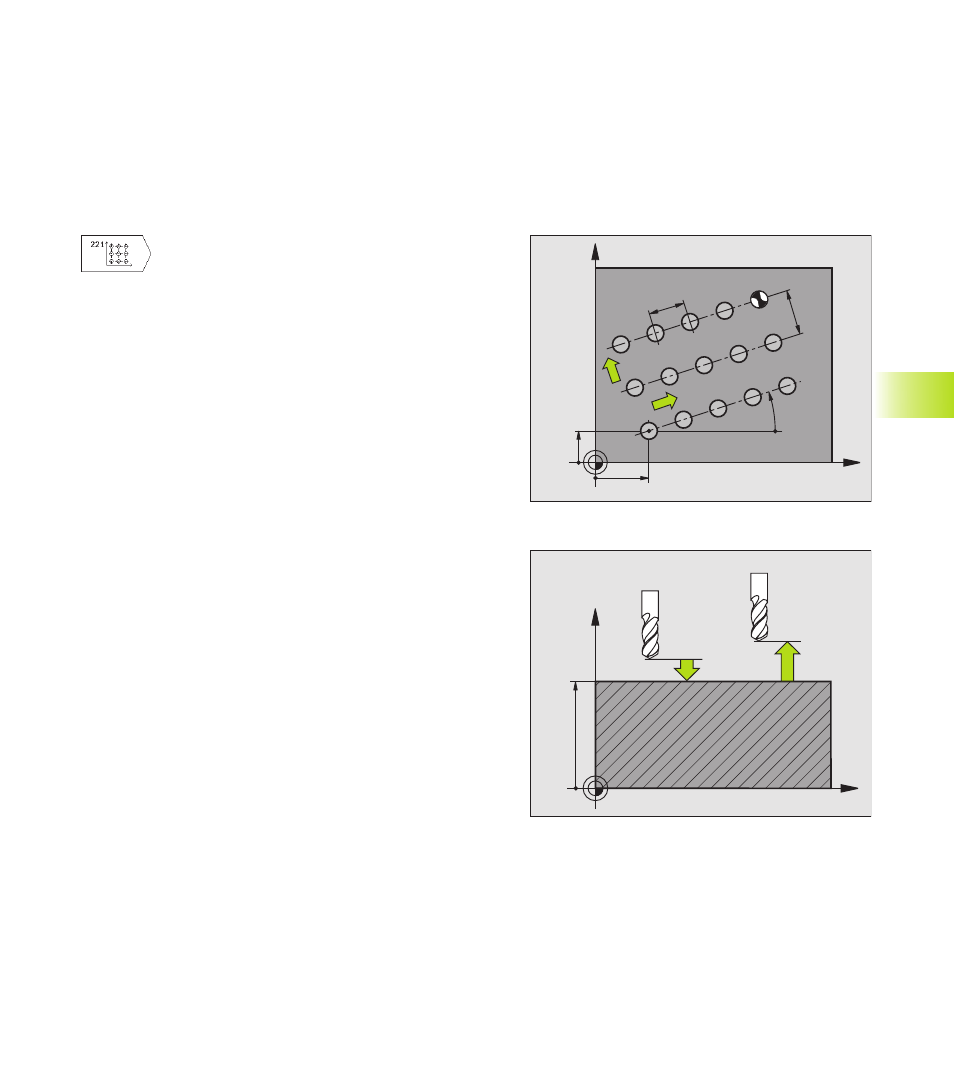
5 The tool subsequently moves to the last point on the second line
where it carries out the machining operation.
6 From this position, the tool approaches the starting point for the
next machining operation in the negative main axis direction.
7 This process (5 to 6) is repeated until all machining operations in
the second line have been executed.
8 The tool then moves to the starting point of the next line.
9 All subsequent lines are processed in a reciprocating movement.
ú
Starting point 1st axis Q225 (absolute value):
Coordinate of the starting point in the main axis of
the working plane
ú
Starting point 2nd axis Q226 (absolute value):
Coordinate of the starting point in the secondary
axis of the working plane
ú
Spacing in 1st axis Q237 (incremental value):
Spacing between the individual points on a line
ú
Spacing in 2nd axis Q238 (incremental): Spacing
between the individual lines
ú
Number of columns Q242: Number of machining
operations on a line
ú
Number of lines Q243: Number of passes
ú
Angle of rotation Q224 (absolute value): Angle by
which the entire pattern is rotated. The center of
rotation lies in the starting point.
ú
Set-up clearance Q200 (incremental value):
Distance between tool tip and workpiece surface.
ú
Workpiece surface coordinate Q203 (absolute
value): Coordinate of the workpiece surface
ú
2nd set-up clearance Q204 (incremental value):
Coordinate in the tool axis at which no collision
between tool and workpiece (clamping devices)
can occur.
8.4 Cy
cles f
or Mac
hining Hole P
at
ter
ns
X
Z
Q200
Q203
Q204
X
Y
Q226
Q225
Q224
Q238
Q237
N = Q242
N = Q243