Data matrix, Control – quick link, Data matrix -7 control — quick-link -7 – Grass Valley SMS-6000 Series User Manual
Page 52: Control — quick-link
2-7
Electrical Connections
Data Matrix
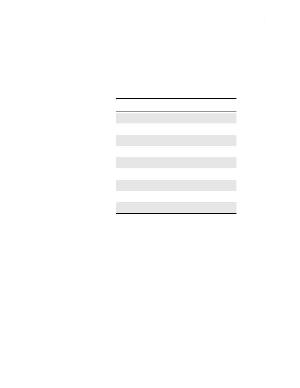
For the correct pinouts for the Data Matrix refer to Table 2-3. Wiring of the
signal conforms to RS422 standard. Mating connectors are available as
options, (SMS-CDRC). Ensure that the cable screen is grounded to
minimize RFI emissions.
Control — Quick-Link
All the frames and remote control panels are connected by a single coaxial
link called Quick-Link. This link uses standard 75
Ω
coaxial cable daisy-
chained from frame to frame and panel to panel. Each end of the link must
be terminated in 75
Ω
. A pair of connectors is fitted to the frames and the
link looped through them; but just one connector is fitted on the panels and
a T-connector is needed to tap off the Quick-Link. In this way a panel can
be removed from service and replaced without disrupting the link, even
temporarily.
This daisy chain method ensures the best transmission quality of the
control signals down the cable. Short cuts which might save cable, such as
running stubs to some panels are not recommended as this may under
certain circumstances cause data errors. The maximum cable stub length is
19.75 in (500mm). The maximum cable length is shown in the Specification
in Section 1: Introduction of this manual
The system can support up to 16 panels and 16 frames. Each unit connected
to the Quick-Link has its own ident switch which is set up as part of the
system setup. The extra Quick-Link connectors on the 3RU Video frame are
not currently supported.
Table 2-3. Data Matrix Pinouts
Input Pins
Signal
Output Pins
Signal
1
GND
1
GND
2
TXA
2
RXA
3
RXB
3
TXB
4
RX 0V
4
TX 0V
5
Not Used
5
Not Used
6
TX 0V
6
RX 0V
7
TXB
7
RXB
8
RXA
8
TXA
9
GND
9
GND