System setup – Grass Valley SMS-6000 Series User Manual
Page 118
A-2
Appendix A — Remote Control Protocol
System Setup
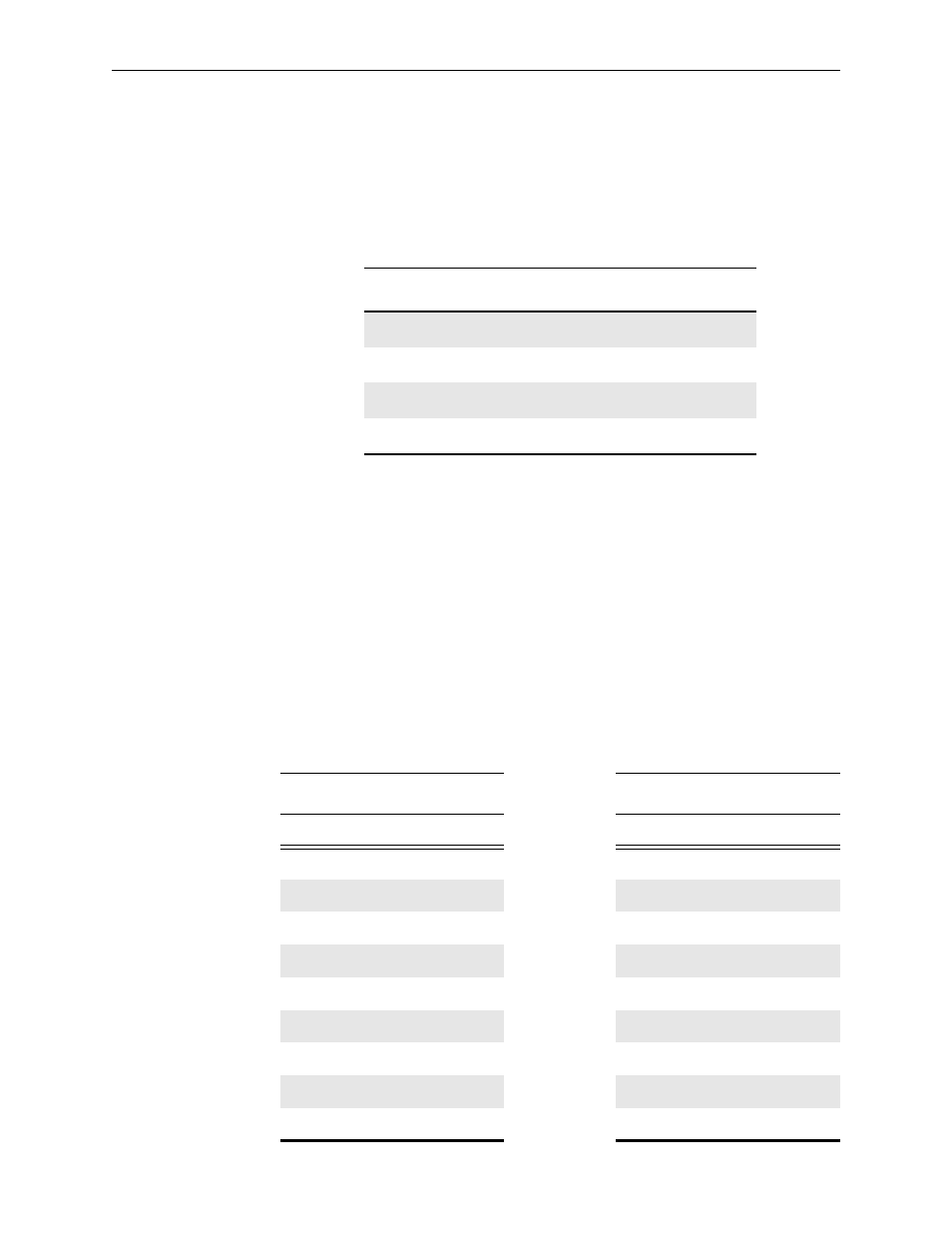
The DIP switches located on the master frame module, must be set as
shown in Table A-1. The port will then respond only to messages of the
correct format. A reply is generated only after a (cr).
The port operates at 9600, 8 data bits, no parity, and 1 stop bit. RS232 or
RS422 are link-selectable on the computer port daughter card PC106 (LK1–
LK5). Toward U3 is RS422. Away from U3 is RS232. Other baud rates and
parity options can be factory selected.
At 9600 baud the system can cope with an overall crosspoint set rate of one
change approximately every 35
µ
s.
The interface connector on the equipment is a 9–pin D socket using the
following pinout. The interface cable only needs to use TX, RX, and GND.
The 24V supply is reserved for Series 6000 equipment only. Refer to
Table A-2.
Table A-1. Dip Switch Settings
DIP Switch Position
Master Frame
Slave Frame
1
UP
UP
2
DOWN
UP
3
DOWN
UP
4
UP
UP
Table A-2. RS232 and RS422 Cable Connections
RS232
RS422
Pin #
Signal
Pin #
Signal
1
CHASSIS
1
CHASSIS
2
RTS
2
TX–
3
RXD
3
RX+
4
N/C
4
RX GND
5
24V High
5
24V High
6
GND
6
TX GND
7
TXD
7
TX+
8
CTS
8
RX–
9
24V LOW
9
24V LOW