Using remote control, Operation – Grass Valley NV8256-Plus v.1.2 User Manual
Page 66
56
Rev 1.2 • 20 Oct 08
4. Operation
Setting Redundant Crosspoint Card Switching
For more information on which signals are controlled by which crosspoint card slot, see
point Card Slots and Managed Signals
on page 5.
3 The selected function will remain active until another button is pressed and a new function
selected.
Using Remote Control
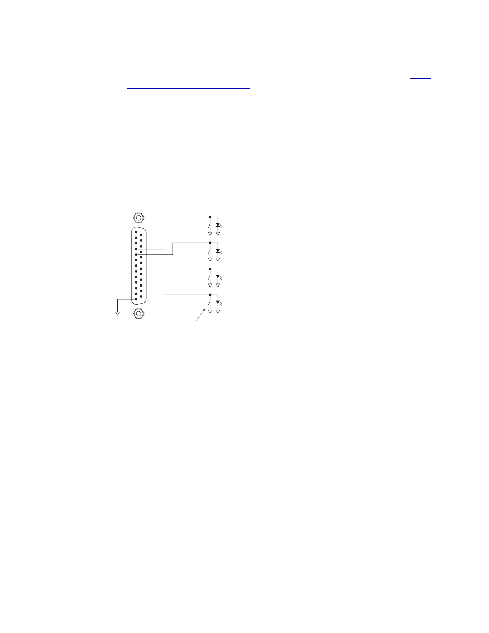
The redundant crosspoint card can be controlled remotely by creating an external circuit. To create
the circuit, use momentary switches with a series resistance of 50
Ω or less. The switches should be
connected in parallel with an LED cathode attached to ground (GND). The output signals are nom-
inally +3.3
V. The selected diode should have a maximum forward bias current of 10
mA and maxi-
mum forward bias voltage of 1.5–2.2 V.
Figure 4-2 shows the remote control connector pinout and required circuit.
Figure 4-2. Redundant Crosspoint Card Connector
Left crosspoint
(Outputs 1128)
Momentary Switches
(Series Resistance < 50W)
1
13
14
25
4
5
6
7
Center Crosspoint
(Redundant)
Right Crosspoint
(Outputs 129256)
Remote Panel Enable