Router control system expansion connections, Video reference, Figure 2-9 – Grass Valley NV8256-Plus v.1.2 User Manual
Page 23: Introduction, Module slots and rear connections
NV8256-Plus Digital Video Router • User’s Guide
13
2. Introduction
Module Slots and Rear Connections
For instructions on making temporary or permanent diagnostic connections, see
on page 42.
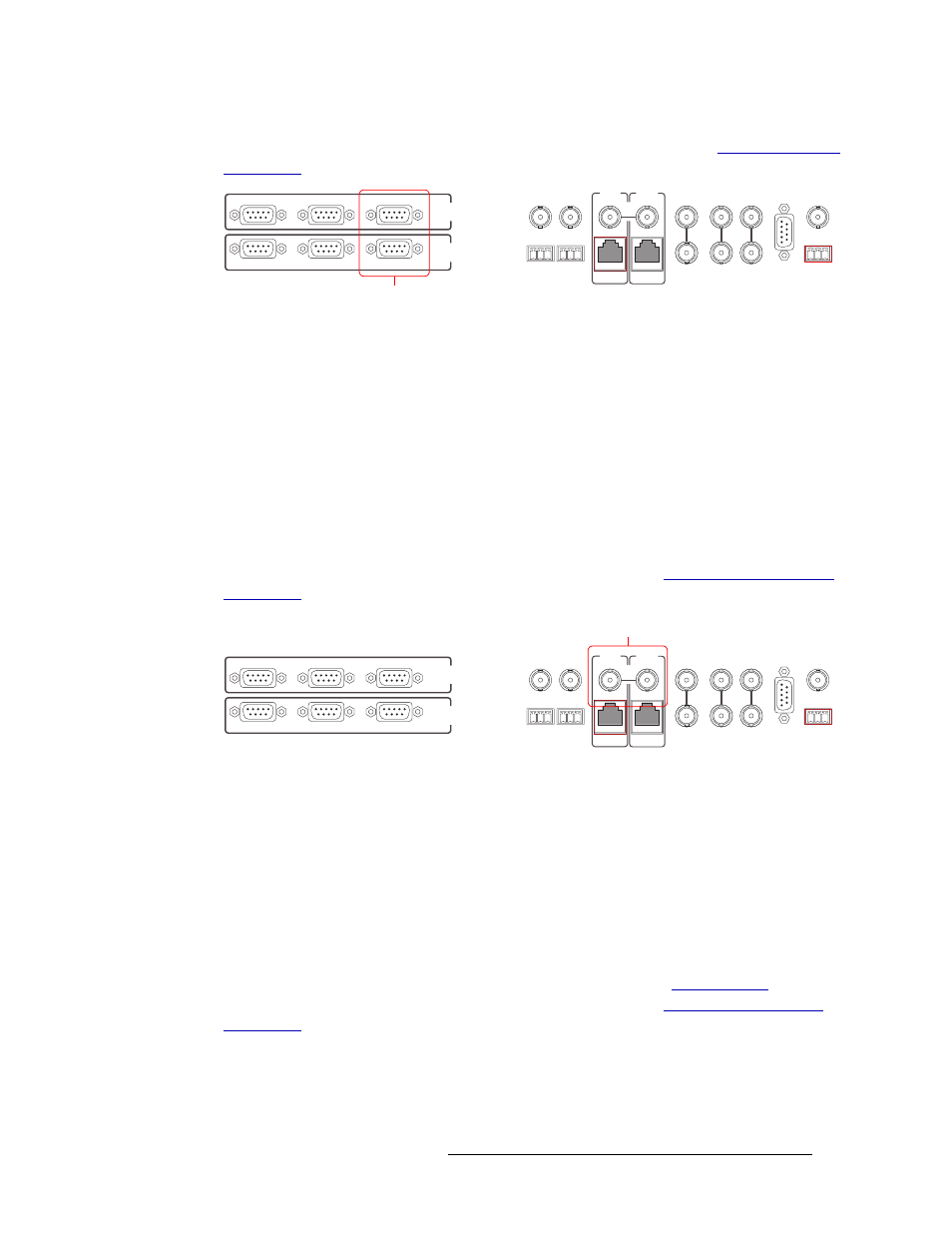
Figure 2-9. Permanent Diagnostic Connections (Rear View)
Router Control System Expansion Connections
In order to manage two connected NV8256-Plus routers, router control system expansion connec-
tions need to be connected between the routers. Router control expansion system connections are
located on the rear of the router, as shown in Figure 2-10.
When making router control system connections, only one router is connected directly to the router
control system. This router acts as the primary router. When making router control system expan-
sion connections, connections from the remaining router, the secondary router, are made to the pri-
mary router. This enables the router control system to communicate with both routers through the
primary router.
For instructions on making control system expansion connections, see
on page 41.
Figure 2-10. Router Control System Expansion Connections (Rear View)
Video Reference
The NV8256-Plus provides timing reference connections for video signals, labeled ‘VIDEO REF
1’ and ‘VIDEO REF 2’, as shown in Figure 2-11. Located on the rear of the router, these connec-
tions provide a reference input for determining the router’s video frame switch point. The video ref-
erence connections require a stable source of PAL, NTSC or tri-level sync.
If a video reference is present, signals switch at the defined frame and line switch points. If a video
reference is not present, the router still performs the switch, but to an internal reference. If a video
reference is not connected, the control card displays a lit red LED. (See
page 60.) For instructions on making video reference connections, see
on page 45.
Redundant and Dual References
There are two video reference connections. The same reference can be used for both connections or
a different reference for each connection. When using the same, or “redundant,” references for both
CTRL 1
CTRL 2
DIAG
CTRL 1
CTRL 2
DIAG
SECONDARY
CONTROL
PRIMARY
CONTROL
SEC
CTRL
PRI
CTRL
AES
REF 1
AES
REF 2
LOOP
THRU
10 B 2
10/100 BT
10 B 2
10/100 BT
VIDEO
REF 2
VIDEO
REF 1
ALARMS
TIME
CODE
NVISION
AUX BUS
LOOP
LOOP
LOOP
Diagnostic
Connections
CTRL 1
CTRL 2
DIAG
CTRL 1
CTRL 2
DIAG
SECONDARY
CONTROL
PRIMARY
CONTROL
SEC
CTRL
PRI
CTRL
AES
REF 1
AES
REF 2
LOOP
THRU
10 B 2
10/100 BT
10 B 2
10/100 BT
VIDEO
REF 2
VIDEO
REF 1
ALARMS
TIME
CODE
NVISION
AUX BUS
LOOP
LOOP
LOOP
Expansion Connections
to Control System