Making router control system connections, Ntrol card(s). see, Making router control sys – Grass Valley NV8256-Plus v.1.2 User Manual
Page 47: Tem connections, Making router, Control system connections, Figure 3-7, Installation
NV8256-Plus Digital Video Router • User’s Guide
37
3. Installation
Making Router Control System Connections
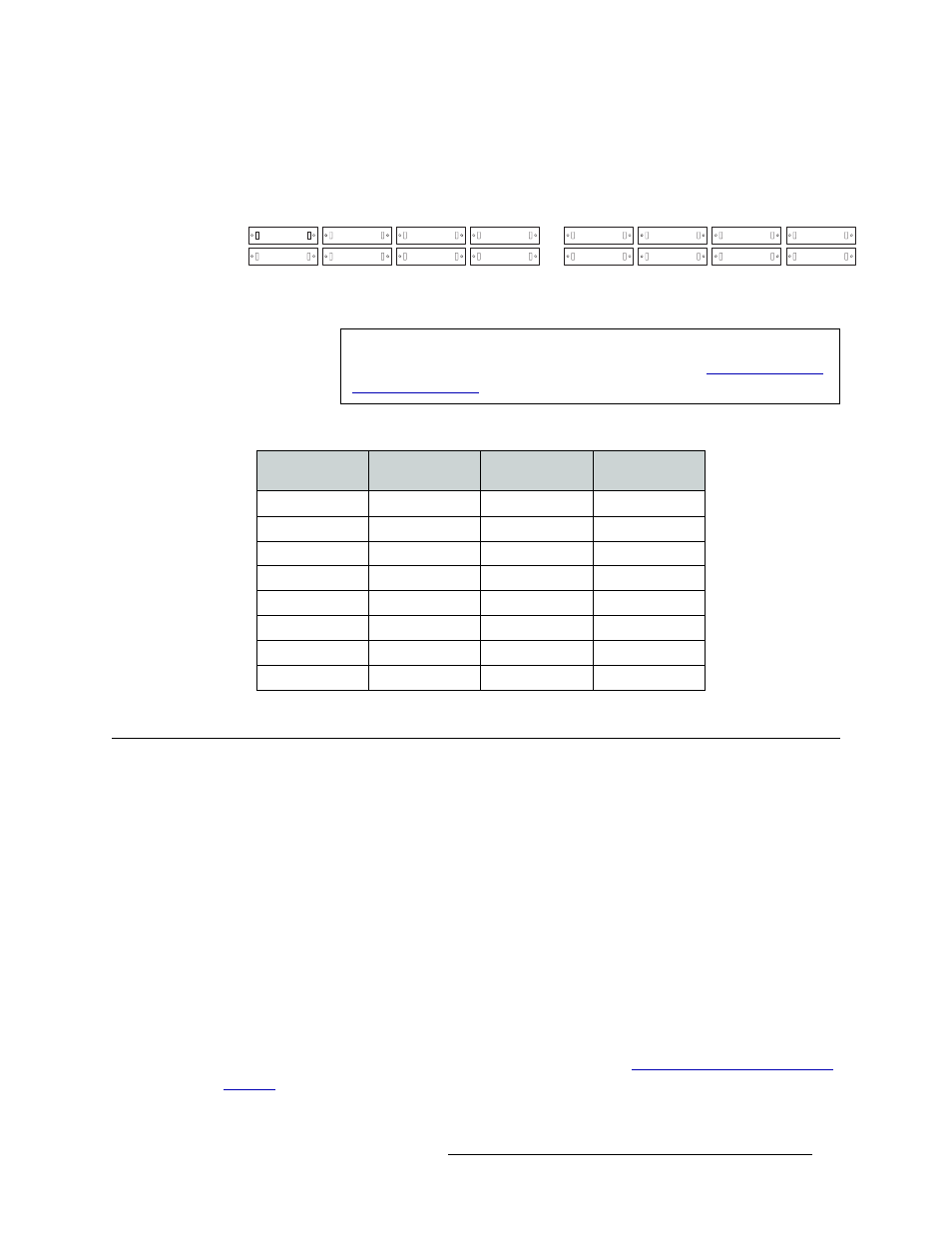
4 Facing the rear of the second router (Router 2), connect the other end of the signal expansion
cable6 to expansion ‘Inputs 449–512’ (A), as shown in Figure 3-7.
Figure 3-7. Expansion Connections on NV8256-Plus Routers (Rear View)
5 Repeat Step 3 and Step 4 until all expansion connections are connected, as follows:
Making Router Control System Connections
To manage signal switching in the NV8256-Plus, connections need to be created between the router
control system and the router.
Connections are as follows:
• Serial Control
—
use to connect to a third-party router control system requiring serial control
connections.
• Ethernet Control
—
use to connect to the NVISION NV9000 router control system and to create
network connections.
• NVISION Aux Bus
—
use to connect to a third-party router control system requiring a GSC
Node Bus connection.
If connecting two NV8256-Plus routers together, only one router is directly connected to the router
control system. This router acts as the primary router. Additional control system expansion connec-
tions are then made between the primary router and the secondary, connected router. This enables
the router control system to communicate with both routers. (See
A
E
B
F
C
G
D
H
E
A
F
B
G
C
H
D
193256
129192
65128
164
193256
129192
65128
164
449512
385448
321384
257320
449512
385448
321384
257320
Router 1
Router 2
Important
Do not force connectors. If a connector does not install easily, stop installa-
tion and contact NVISION. For contact information, see
Router 1
Router 2
Inputs on
Router 1
Inputs on
Router 2
A
A
193–256
449–512
B
B
129–192
385–448
C
C
65–128
321–384
D
D
1–64
257–320
E
E
449–512
193–256
F
F
385–448
129–192
G
G
321–384
65–128
H
H
257–320
1–64