Installation – Grass Valley NV8256-Plus v.1.2 User Manual
Page 41
NV8256-Plus Digital Video Router • User’s Guide
31
3. Installation
Making Power Connections
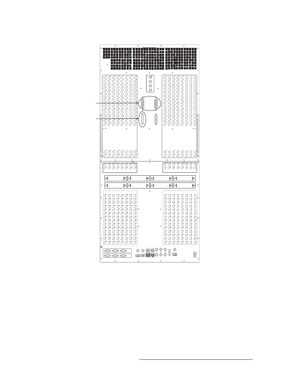
Figure 3-2. Power Supply Connections and Power Supply Monitor Connection on Router (Rear View)
5 Facing the rear of the NV6257, using the remaining power supply cable, connect to ‘Output
Power 2’, as shown in Figure 3-1 on page 30.
6 Facing the rear of the router, connect the other end of the power supply cable to ‘Power Input
2’, as shown in Figure 3-2.
7 Facing the rear of the NV6257, connect one end of the monitor cable (WC0046-00) to the
‘Power Supply Monitors’ DB25 connection, as shown in Figure 3-1 on page 30.
8 Facing the rear of the router, connect the other end of the monitor cable to ‘Power Supply
Monitor’, as shown in Figure 3-2.
OUTPUTS 129-256
OUTPUTS 1-128
INPUTS 129-256
INPUTS 1-128
ROUTER
EXPANSION
PORTS
INPUTS 1-128
INPUTS 129-256
Power Supply
Monitor
Connection
from NV6257
Power Supply
Connections
from NV6257
(Power Input 1
and
Power Input 2)