Slots and corresponding signal numbers, Slots and corresponding, Signal numbers – Grass Valley NV8256-Plus v.1.2 User Manual
Page 19: Introduction, Module slots and rear connections
NV8256-Plus Digital Video Router • User’s Guide
9
2. Introduction
Module Slots and Rear Connections
Slots and Corresponding Signal Numbers
If the NV8256-Plus router is used as a standalone router, up to 256 incoming signals can be
received and up to 256 outgoing signals distributed. The crosspoint card installed in the left cross-
point card slot manages inputs 1–256. If two NV8256-Plus routers are connected together, signals
coming into one router can be sent to a second, connected router. This can double the number of
signals managed by the two routers to a maximum of 512 inputs and 512 outputs. The crosspoint
card installed in the right crosspoint card slot manages inputs from the second router: 257–512.
A crosspoint card installed in the middle slot acts as a redundant crosspoint card for fail-over. For
more information on crosspoint cards, see
Crosspoint Card Slots and Managed Signals
For information on installing cards in modules slots, see
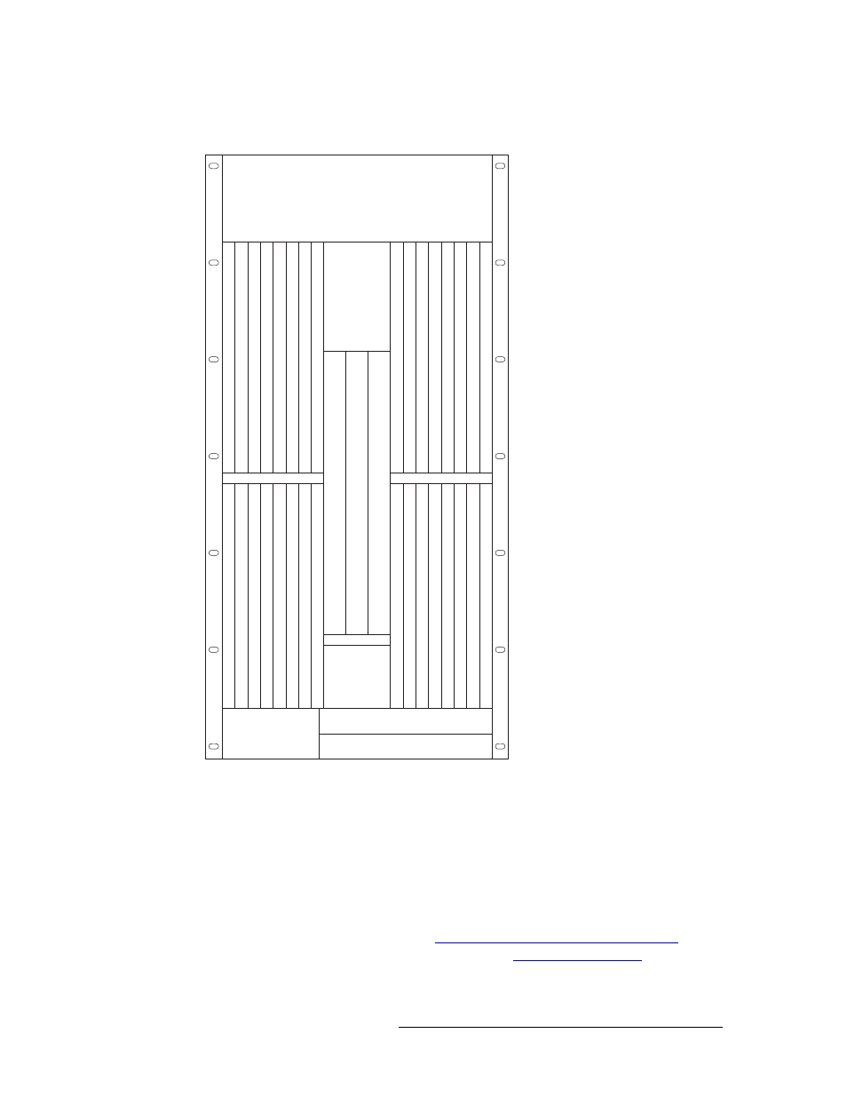
Figure 2-3. Inputs and Outputs, Numbers Assigned (Front View)
Each input card slot and output card
slot, and the card it holds, receives or
distributes signals through 16 BNC
connectors. Each signal is assigned a
number that corresponds to the physi-
cal input or output connection. The
numbers correspond to the slot in
which an input card or output card is
installed. This means that input slot 1
corresponds to inputs 1–16, input slot
2 corresponds to inputs 17–32, and so
on, up to 256, as shown in Figure 2-3.
Output slots are similarly numbered,
such that output slot 1 corresponds to
outputs 1–16, output slot 2 corre-
sponds to outputs 17–32, and so on,
up to 256, as shown in Figure 2-3.
Similarly, the location of an input card
or output card in the router frame
determines the inputs and outputs
managed by that card. For example,
an input card located in slot 1 man-
ages inputs 1–16. An input card
located in input slot 2 manages inputs
17–32, and so on.
Control CardPrimary
OUTPUTS 129-144
OUTPUTS 145-160
OUTPUTS 161-176
OUTPUTS 177-192
OUTPUTS 193-208
OUTPUTS 209-224
OUTPUTS 225-240
OUTPUTS 241-256
INPUTS 129144
INPUTS 145160
INPUTS 161176
INPUTS 177192
INPUTS 193208
INPUTS 209224
INPUTS 225240
INPUTS 241256
OUTPUTS 116
OUTPUTS 1732
OUTPUTS 3348
OUTPUTS 4964
OUTPUTS 6580
OUTPUTS 8196
OUTPUTS 971
12
OUTPUTS 1
13128
INPUTS 116
INPUTS 1732
INPUTS 3348
INPUTS 4964
INPUTS 6580
INPUTS 8196
INPUTS 971
12
INPUTS 1
13128
MONIT
OR
FAN
CROSSPOINT
INPUTS 1-256
CROSSPOINT
(REDUNDANT)
CROSSPOINT
INPUTS 257-512
Control CardSecondary