Signal expansion connections, Signal expansion, Connections – Grass Valley NV8256-Plus v.1.2 User Manual
Page 46: Installation, Making signal connections, 8) expansion connectors (with cover plates
36
Rev 1.2 • 20 Oct 08
3. Installation
Making Signal Connections
4 Locate the output connections on the rear of the router, as shown in Figure 3-5. There are 16
columns of 16 BNC connections each.
5 For each output, connect to each output connection using a 75
Ω BNC connector and coaxial
cable.
6 Connect the other end of the cable to the distribution destination for the outgoing signal.
7 If connecting two NV8256-Plus routers together, connect the signal expansion connections.
, following.)
Signal Expansion Connections
As a standalone router, the NV8256-Plus can manage up to 256 inputs and 256 outputs. Using the
NV8256-Plus signal expansion connections two routers can be connected, increasing the number of
signals managed up to 512 inputs and 512 outputs. Connected routers must be situated physically
next to each other, either top to bottom or side to side.
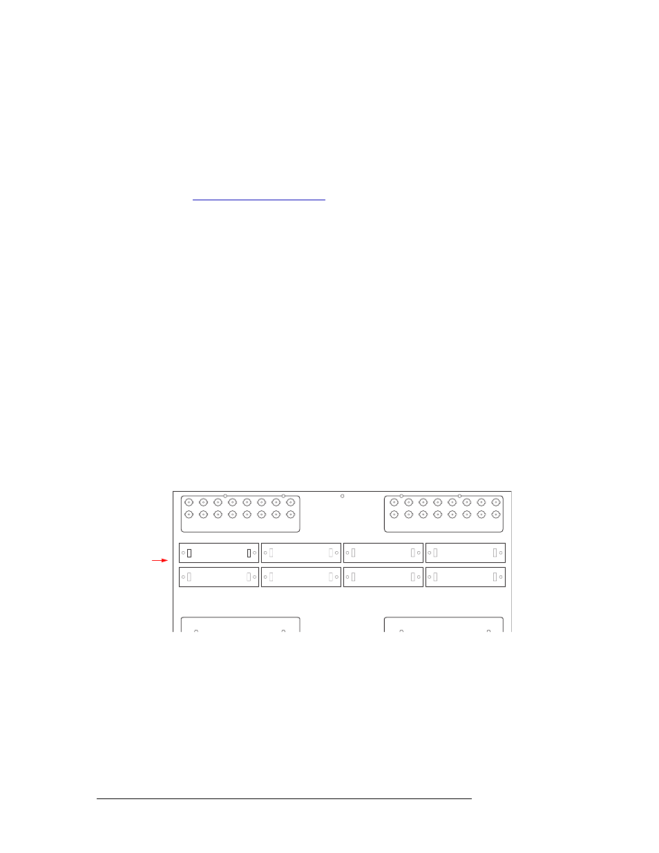
The NV8256-Plus contains 8 expansion connections, located on the rear of the router. All 8 expan-
sion connections must be connected to properly connect two frames together. Each signal expan-
sion connection manages 64 inputs. The connections are labeled according to the signals managed:
‘Inputs 1–64’, ‘Inputs 65–128’, and so on up to 512 signals. (See Figure 2-2 on page 8.) Facing the
rear of the router, the signals are labeled in descending order from right to left.
The signal expansion connections use proprietary expansion cables provided by NVISION
(WC0056-00).
How to Make Signal Expansion Connections between Two Routers
1 Locate the signal expansion connections on the rear of the two router frames being connected,
as shown in Figure 3-6. The routers should be located close together.
The signal expansion connections are labeled ‘Router Expansion Ports’.
Figure 3-6. Expansion Connections for Connecting Two NV8256-Plus Routers
2 Using a screwdriver, remove the cover plates covering the signal expansion connections.
3 Facing the rear of the first router (Router 1), connect the signal expansion connector
(WC0056-00) to expansion connection ‘Inputs 193–256’ (A), as shown in Figure 3-7.
INPUTS 385 - 448
INPUTS 449 - 512
INPUTS 129-256
131
147
163
179
195
211
227
243
8
2
1
-
1
S
T
U
P
N
I
6
5
2
-
9
2
1
S
T
U
P
N
I
ACTIVE LOOPTHRU
OF INPUTS 129 - 192
ACTIVE LOOPTHRU
OF INPUTS 193 - 256
130
129
146
145
162
161
178
177
194
193
210
209
226
225
242
241
ROUTER
EXPANSION
PORTS
ACTIVE LOOPTHRU
OF INPUTS 1 - 64
ACTIVE LOOPTHRU
OF INPUTS 65 - 128
34
33
50
49
66
65
82
81
98
97
114
113
INPUTS 257 - 320
INPUTS 321 - 384
2
1
18
17
INPUTS 1-128
3
19
35
51
67
83
99
115
(8) Expansion
Connectors (with
Cover plates