Making video reference connections, Making monitor connections, Making video reference – Grass Valley NV8256-Plus v.1.2 User Manual
Page 55: Connections, Making monitor connec, Tions, Making video ref, Erence connections, Making mon, Itor connections
NV8256-Plus Digital Video Router • User’s Guide
45
3. Installation
Making Video Reference Connections
4 If a secondary (optional for redundancy) control card is installed, connect to the ‘DIAG’ con-
nection in the ‘SECONDARY CONTROL’ section using a DE9 connector and a serial cable as
described in Step 2 and Step 3. For more information, see
Making Video Reference Connections
The NV8256-Plus provides timing reference connections for analog video signals, labeled ‘VIDEO
REF 1’ and ‘VIDEO REF 2’. The control card uses these references to perform takes at the proper
point in time (per SMPTE RP168), determining the router’s video frame switch points. The video
reference connections require a stable source of PAL, NTSC or tri-level sync. Both video reference
connections use 75
Ω BNC connectors and coaxial cable. For a detailed description of the video ref-
erence connections, see
on page 13.
Each ‘VIDEO REF’ connection can be use the same reference source (redundant) or two unique
reference sources (dual). For more information, see
If a video reference is present, signals switch at the defined frame and line switch points. If a video
reference is not present, the router performs takes using an internally generated reference signal and
the control card displays a lit red LED. (See
How to Make Connections to the Video References
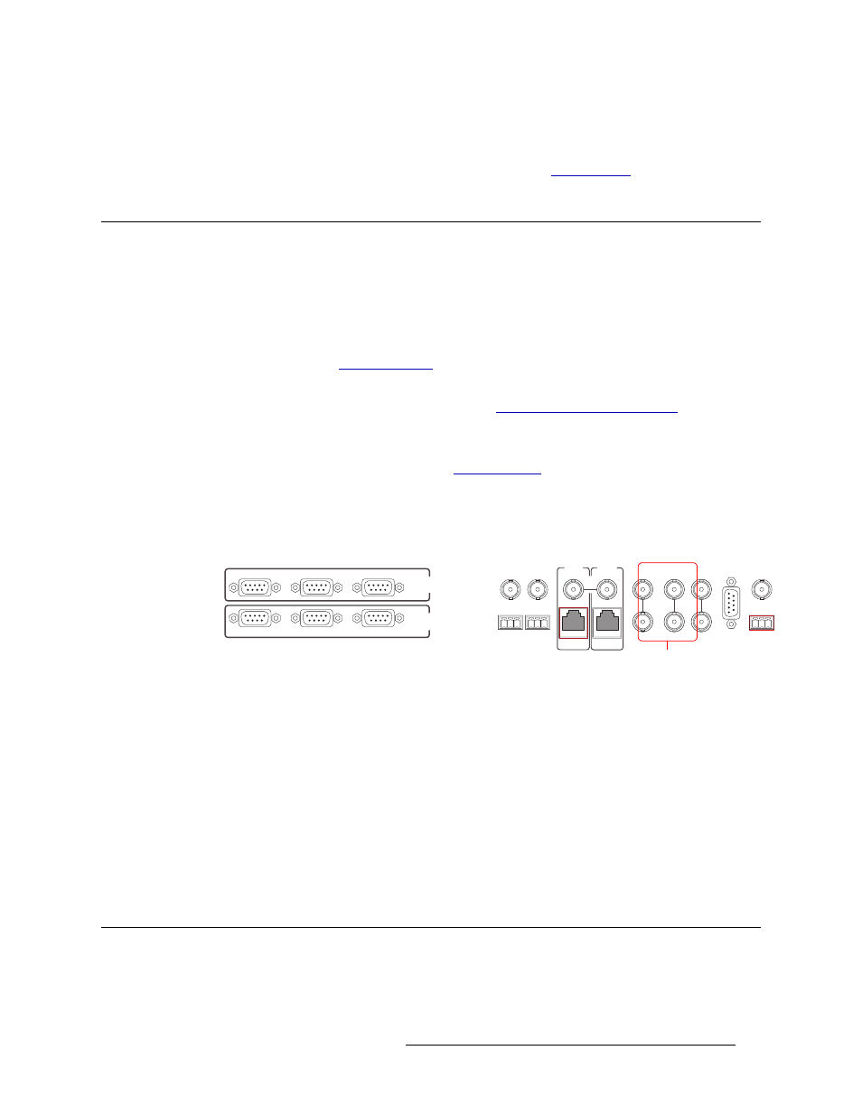
1 Locate the video reference connections on the rear of the router, as shown in Figure 3-13. Video
reference connections are labeled ‘VIDEO REF 1’ and ‘VIDEO REF 2’.
Figure 3-13. Video Reference Connections (Rear View)
2 Connect to the ‘VIDEO REF 1’ connection using a 75
Ω BNC connector and coaxial cable.
3 Connect the other end of the cable to a reference signal. Be sure the incoming signal is from a
stable source. The signals can be:
PAL
NTSC
Tri-level sync (1080i 50, 59.94, 60 and 720p 50, 59.94, 60)
4 On all unused video reference connections, be sure to terminate the loop-through by installing a
75
Ω BNC terminator.
5 Connect to the ‘VIDEO REF 2’ input connection, as described in Steps 2 through 4.
Making Monitor Connections
The monitor connections on the rear of the NV8256-Plus enable the monitoring of outgoing sig-
nals. The monitor connections forward signals from the monitor card, which receives one signal
CTRL 1
CTRL 2
DIAG
CTRL 1
CTRL 2
DIAG
SECONDARY
CONTROL
PRIMARY
CONTROL
SEC
CTRL
PRI
CTRL
AES
REF 1
AES
REF 2
LOOP
THRU
10 B 2
10/100 BT
10 B 2
10/100 BT
VIDEO
REF 2
VIDEO
REF 1
ALARMS
TIME
CODE
NVISION
AUX BUS
LOOP
LOOP
LOOP
Video Reference
Connections