Installation – Grass Valley NV8256-Plus v.1.2 User Manual
Page 54
44
Rev 1.2 • 20 Oct 08
3. Installation
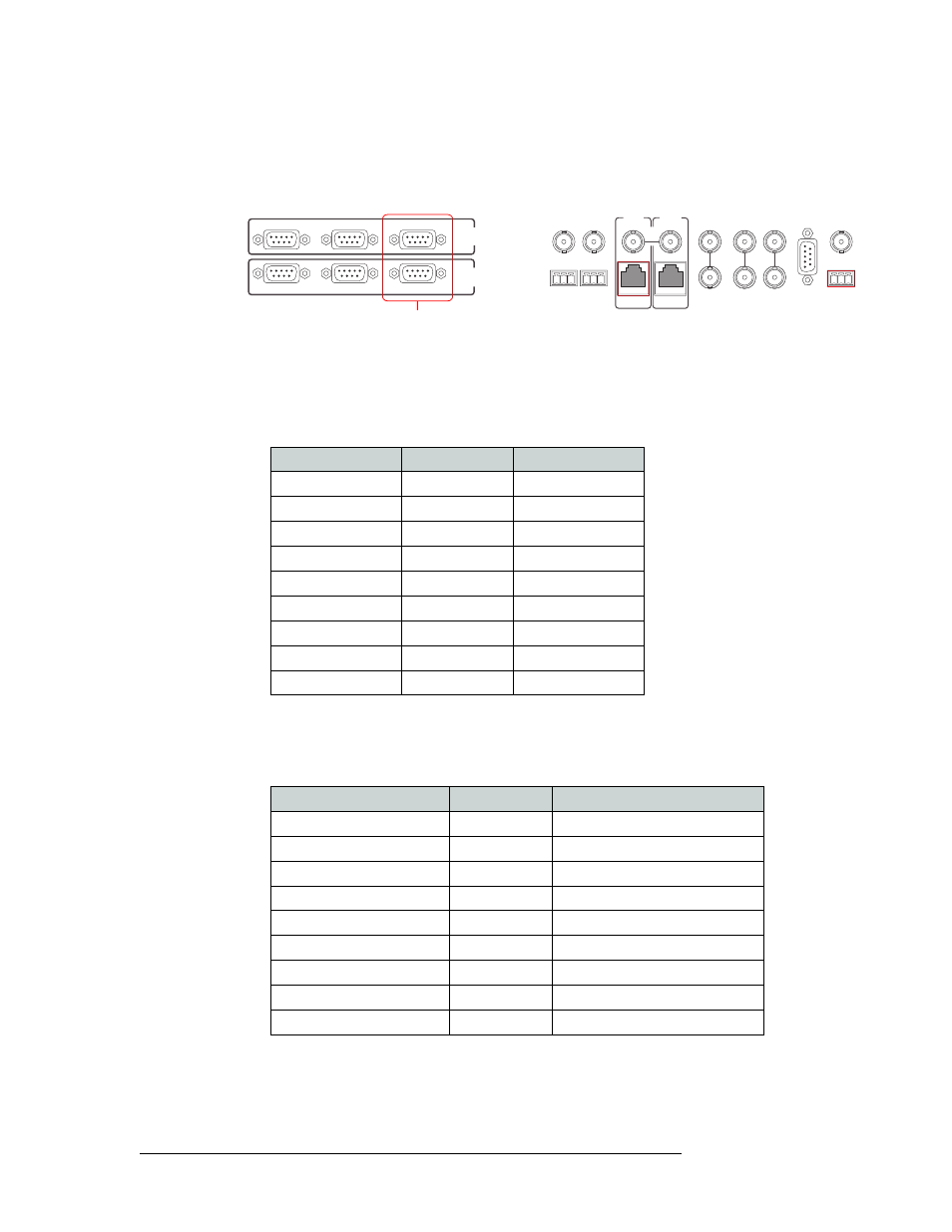
Making Diagnostic Connections
How to Make Permanent Diagnostic Connections:
1 Locate the diagnostic connections on the rear of the router, as shown in Figure 3-12. The diag-
nostic connections are labeled ‘DIAG’.
Figure 3-12. Diagnostic Connections (Rear View)
2 Connect to the ‘DIAG’ connection in the ‘PRIMARY CONTROL’ section using a DE9 connec-
tor and a serial cable. The ports are set for RS-232, but you can also use RS-422:
• The following lists the DE9 pin connectors for RS-232:
• The DE9 connector can be set for RS-422, but adjustments will need to be made in
UniConfig. For more information, see the UniConfig User’s Guide.
The following lists the DE9 pin connectors for RS-422:
3 Connect the other end of the cable to the PC running the UniConfig application.
CTRL 1
CTRL 2
DIAG
CTRL 1
CTRL 2
DIAG
SECONDARY
CONTROL
PRIMARY
CONTROL
SEC
CTRL
PRI
CTRL
AES
REF 1
AES
REF 2
LOOP
THRU
10 B 2
10/100 BT
10 B 2
10/100 BT
VIDEO
REF 2
VIDEO
REF 1
ALARMS
TIME
CODE
NVISION
AUX BUS
LOOP
LOOP
LOOP
Diagnostic
Connections
PC End (DCE)
Pin Numbers
Router End (DTE)
DCD
1 ------------1
Ground
RXD
2 ------------2
TXD
TXD
3 ------------3
RXD
DTR
4 ------------4
DSR
Signal Ground
5 ------------5
Signal Ground
DSR
6 ------------6
DTR
RTS
7 ------------7
CTS
CTS
8 ------------8
RTS
Ground
9 ------------9
Ground
PC End
Pin Numbers
Router End
Ground
1 ------------1
Ground
Rx–
2 ------------2
Tx–
Tx+
3 ------------3
Rx+
Tx Common
4 ------------4
Rx Common
N/C
5 ------------5
N/C
Rx Common
6 ------------6
Tx Common
Rx+
7 ------------7
Tx+
Tx–
8 ------------8
Rx–
Ground
9 ------------9
Ground