Router ip address, Temporarily connecting to uniconfig, Permanently connecting to uniconfig – Grass Valley NV8256-Plus v.1.2 User Manual
Page 53: Onfig. (see, Temporarily con, Necting to uniconfig, Installation
NV8256-Plus Digital Video Router • User’s Guide
43
3. Installation
Making Diagnostic Connections
Router IP Address
If you are using an Ethernet connection between the router and the router control system, an IP
address for the router needs to be set on the control card. The IP address is set using UniConfig.
However, the PC running UniConfig cannot communicate with the router until an IP address for the
router is entered. To solve this problem, a temporary diagnostic connection to UniConfig can be
created, enabling you to enter the IP address before completing all router connections and configu-
rations. (See
Temporarily Connecting to UniConfig
on page 43.) After an IP address is entered, the
temporary diagnostic connection can be disconnected and a permanent diagnostic connection
made. (See
Permanently Connecting to UniConfig
on page 43 and
Temporarily Connecting to UniConfig
A temporary connection is created through the DE9 port located on the front of the primary control
card. The baud rate for this port is locked to 9600.
How to Make Temporary Diagnostic Connections
1 Locate the primary control card slot, as shown in Figure 2-2 on page 8. When facing the front
of the router, the control cards are located in the lower, right-hand section.
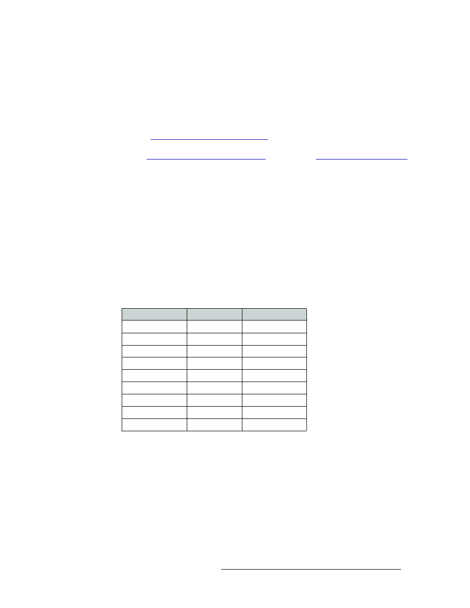
2 On the front of the control card, connect to the serial port using a DE9 connector and a serial
cable. The following lists the DE9 pin connectors for RS-232:
3 Connect the other end of the cable to the PC running the UniConfig application using a DE9
connector. (See Figure 3-19 on page 50.)
4 Using UniConfig, enter the IP address for the Ethernet control system connection.
5 When done configuring, remove the temporary connection.
Permanently Connecting to UniConfig
There are two diagnostic ports located on the rear of the router, labeled ‘DIAG’. The diagnostic
ports default to 38,400 baud, RS-232, but can be set to RS-422 using UniConfig. For more informa-
tion, see the UniConfig User’s Guide.
PC End (DCE)
Pins
Router End (DTE)
DCD
1 ------------1
Ground
RXD
2 ------------2
TXD
TXD
3 ------------3
RXD
DTR
4 ------------4
DSR
Signal Ground
5 ------------5
Signal Ground
DSR
6 ------------6
DTR
RTS
7 ------------7
CTS
CTS
8 ------------8
RTS
Ground
9 ------------9
Ground